Control System Savvy
By Tony Bingelis (originally published in Sport Builder, September 1993)
All pilots know how aircraft control systems work, and how to operate them.
But for the homebuilder pilot, that knowledge only scratches the surface. He must also figure out how to make and install the individual components and how to make them all work correctly.
Furthermore, he must assure himself that his control system is a reliable one . . . unfortunately, that will probably remain an unproven quality until after the aircraft has been flight tested.
The best way to assure a high degree of control system reliability, before that all important test flight, is by implementing traditional control system standards for its installation, operation, inspection and maintenance.
Control System Options
In homebuilts, control surfaces are usually operated by cables, or by a combination of cables and push-pull tubes.
Which of the two methods of operating the controls do you think is the best?
When we say "best," what do we really mean? The lightest? The least expensive? Easiest to build and install? The strongest? The most friction free? The most reliable?
If you are building from plans, or from a kit, the best aircraft flight control system is the one the designer designed for the airplane.
On the other hand, if you are building an airplane of your own design, you will have to decide which flight control system option will best suit your design and its needs.
Most homebuilt designs quite effectively incorporate both cables and push-pull tubes for activating the different control functions.
Look over a number of aircraft and here’s what you will find:
Rudders are almost exclusively cable operated. This is because cables provide the simplest, lightest, and most reliable rudder control system you can install.
Incidentally, you may have noticed that older designs, particularly the high wing monoplanes and biplanes, also utilize cables for operating the elevators and ailerons . . . with the help of numerous pulleys.
Unfortunately, when a lot of pulleys are necessary for routing the cables, the control system tends to develop more resistance in the control stick, making it feel "heavy on the controls."
Present day practice relies more on the use of push-pull tubes and rods than cables for controlling both the elevators and the ailerons. This combination of cables and push-pull tubes results in a very light efficient installation, especially in low wing aircraft.
In my opinion, the mechanical means used (cables, push-pull tubes, or a combination) to operate the controls is not nearly as important as the way the system is installed. Both control system options are reliable when correctly installed and the control surfaces are properly rigged.
Rigging Control Surfaces
How much up-elevator travel do you need? How about the other control surfaces? How much flap deflection is too much?
Here again, if you are building a kitplane, or are building from plans, all the control surface travel limits are given (or should be given) for the design.
If you can’t find that information, you might initially adopt some of the typical control travel limits normally utilized in many conventional aircraft.
You should understand, however, that these so-called "typical control travel limits" may or may not be the ideal limits for your particular design, but they do provide a good starting point.
For example, some aircraft may have a very limited up-travel for the elevator. The idea being to minimize the risk of inadvertent stalls and spins. Obviously, if you are building an aerobatic machine, such a limited "up" travel would be unthinkable.
The weight and balance are two important factors which can also influence the control travel limits that will be needed.
Differential Aileron Travel
The older lightplanes were often called "rudder airplanes" because so much rudder input was needed in maneuvering the aircraft. The reason for this can be attributed to the way the ailerons were operated. That is, the degree of aileron travel provided was the same "up" as it was "down." Unfortunately, this results in an odd and most noticeable flight reaction when you try to make a simple banked turn. Let me explain.
In making a banked turn to the right, for example, the aileron on the right wing is deflected up. Unfortunately, the left aileron is deflected down the same amount creating a lot of drag on that side. This tends to skew the nose of the aircraft to the left . . . opposite to the direction you intend to turn to. The next result is that you have to punch in extra right rudder to keep that banked airplane turning to the right.
I don’t know why any designer would consider designing such installations any more.
Differential aileron travel is one means used to eliminate this type of primitive control reaction. It is mechanically simple to provide the ailerons with more up travel than down travel. This greatly reduces the adverse drag created by the down aileron.
Such an arrangement effectively negates the need for the use of extra rudder pressure in a turn. With properly designed aileron bell cranks you can make coordinated turns with the control stick alone . . . and that is the way to go.
About Those Flaps
The beneficial gain in lift coefficient realized with the deployment of flaps appears to peak when flaps are lowered as much as 40 degrees. A maximum flap travel of 45 degrees, therefore, should be the set limit for full flaps because flap drag increases rapidly beyond that recommended 40 degree deflection.
If at all practical, stay with manually operated flaps. They are simpler, more reliable, and can be deployed and dumped fast.
Electric flaps are slow acting and cannot be dumped quickly after landing. About the only positive electric flaps feature, as I see it, is the infinite number of flap settings possible . . . but who needs that? By contrast, manual flaps are usually limited to two or three settings, say, 10, 20, 30 degrees and full flaps.
Typical Travel Limits For Control Surfaces
- Ailerons - 20 degrees up and 15 degrees down.
- Rudder - 25 degrees left and right.
- Elevator - 22 degrees up and 15 degrees down.
- Flaps - Limited to 40 degrees.
Control Stops
Don’t overlook the importance of installing positive mechanical control stops, both at the external flight control surfaces and in the cockpit at the control stick and rudder pedals.
If you only install control stops at the flight control surfaces you may, during some exciting moment, apply so much pressure to the rudder pedals or control stick that you might overstress and fail the linkage or one of the control surfaces.
Controls Too Sensitive?
Many a builder is dismayed to learn how sensitive the controls are in his homebuilt. The embarrassing consequence being that the pilot over-controls in spite of himself and causes the airplane to behave more like a porpoise than an arrow in flight.
Don’t make the mistake of shortening your control stick . . . at least not until you have flown the airplane. The shorter the stick the more sensitive (quicker) the airplane response to even the slightest movement of the control.
The Falco I built had one of the longest control sticks (sort of like a brake lever on a buckboard) ever to grace a homebuilt . . . consequently, there never was any risk in my overcontrolling that beauty. Even so, there were some folks who thought it was too sensitive. Maybe so, compared to a sedate Wichita "Chug-a-long," but not compared to most any high performance homebuilt.
Another place where sensitivity in the control system originates is the geometry of the control horns, bell cranks, and control stick connections.
Play In The Control System
Check your controls for lost motion (play) in the control system.
To do this, immobilize the control stick or have someone hold it, while you wiggle each control surface in turn. Also check the trim tab.
There should be little or no play at the trailing edges. The more play there is, the greater the potential for the onset of flutter under some flight conditions.
It is more difficult to install a push-pull type control system without any play in it, than it is to install a cable operated one. Therefore, take extra care in drilling all bolt holes to ensure a snug fit at each control connection.
About Control Balance
Not all control surfaces must be balanced. However, if your design requires the ailerons, elevator and rudder to be balanced, by all means do so.
Rudders are seldom balanced 100%. Ailerons may or may not be 100% balanced. However, elevators, if balanced at all, will normally be 100% balanced.
Ordinarily, it is far safer to overbalance a control surface than it is to skimp on the required weight.
In that control surfaces are subject to flutter, it is important not to add unnecessary weight aft of their hinge axes.
This means, too, you should avoid adding too many coats of paint to the control surfaces.
Also, don’t forget to re-balance the control surface if you plan to bury an electric trim motor in the elevator or ailerons.
Use The Correct Hardware
A separated control connection in flight can result in frightening if not disastrous consequences. Having controllable trim tabs but lacking the skill and luck needed to effect some control with them, in such an emergency, may only prolong the inevitable.
This means that each connection you make must be carefully rechecked after its initial installation to:
- Assure yourself that each control surface moves in the correct direction.
- Assure yourself that you installed the correct hardware for each connection.
- Assure yourself that there is no possibility that any part of the control system will rub or chafe against any part of the structure.
You can safely route control cables through bulkheads by using phenolic bushings or nylon guides to protect the cable against abrading against any metal surface.
Remember, you may have to someday remove the cables, so be sure the bushings are large enough to allow the end terminals to be pulled through.
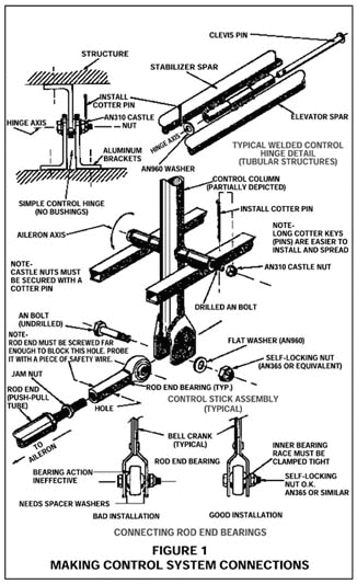
Certain control system connections must be made using drilled bolts and castle nuts . . . each of which must be safetied with a cotter pin (see Figure 1).
Other connections can be safely made using self-locking nuts.
Here’s what determines which type of nut you may use . . . and where.
- Any connection where there is movement between the bolt head, or nut, and the fitting in which it is installed requires the use of a castle nut locked with a cotter pin. A self-locking nut might loosen in such a location.
- The other type of connection, one where there is no movement between the bolt head and/or nut, can be installed with a self-locking nut. This condition is usually met when a rod end bearing or a similar bearing type connector is installed (see Figure 1).
Lubrication
You will find it easier to lubricate the rod end bearings, hinges and bushings as each of these assemblies is installed. This is especially true where castle nuts and cotter pins must be used.
Some locations (rudder pedals, for example) make it difficult to see when the cotter pin hole is aligned. You can spend a frustrating hour trying to reinstall a couple of cotter pins in castle nuts.
You will find longer cotter pins are easier to install and spread when access is limited. Try one and see for yourself.
Control Gap Seals
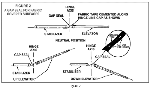
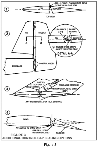
The effectiveness of some flight controls (elevator, aileron and rudder) may be improved by sealing the wide open gap formed by the hinge installation.
A number of methods can be used to do the job if your particular aircraft design has similar "see-through" hinge lines (seeFigures 2 and 3).
Final Control System Check
Move each control through its entire range of movement from one stop to the other. Verify once more that each control surface moves in the correct direction. All controls must move smoothly to their limits without binding.
You don’t hear any squeaky noises or feel any sign of rubbing? Congratulations!


