First Flights - Ralph Wise’s GT-400
By Brett Hahn
-
-
Photos by John Rustuen and Kathi Wise -
February 2016
The Test
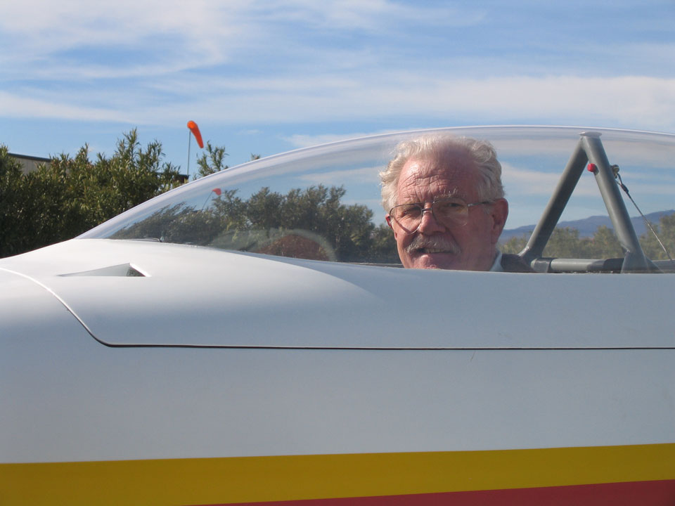
As the morning sun crept over the mountains, 63-year-old Ralph Wise lowered himself into the cockpit of his custom-designed and -built, hybrid-composite GT-400. Like a pea settling into the snug pod, he snapped the safety harness together and cinched it tight. He fastened his helmet, slipped on well-worn gloves, and lowered the canopy. Checklist in hand, Ralph methodically checked every item. On the ramp, the roar of an Italian Marchetti 260 broke the morning silence as chase pilot Dan Canin taxied into view.
Master switch on, fuel pump on, engine start—the Continental IO-520 shuddered and shook, then growled to life. The whole airframe vibrated with energy. Ralph smiled, gave Dan a thumbs-up, and they taxied out to Mojave airport’s long Runway 30. The sun was higher now.
After a thorough warm-up and system check, Ralph added takeoff flaps. He contacted the tower for permission to launch. It was granted and best wishes were conveyed. Ralph advanced the throttle and the GT-400 moved forward smartly. He pushed the throttle wide open and the runway rushed under him. The engine’s tachometer wound up and the big prop’s thrust pushed him back into the seat. The airspeed indicator came alive, and Ralph gently eased the control stick back. The GT-400 lifted smoothly off the runway for the first time and climbed up over the yellow desert at more than 1,000 feet per minute.
Leaving the GT-400’s gear down for this first test flight, Ralph and Dan climbed to 8,000 feet and leveled off. Ralph used test cards prepared by Dan and Don Saint, both Lockheed engineers. Slow flight characteristics were explored. Low speed stability was good. The engine was cooling properly and oil temps were acceptable. Time to land.
Ralph slowed to enter the pattern with the Marchetti tucked in, observing his every move. The fowler flaps are mechanically actuated and he pulled on the lever to drop them down. He turned for final, gear still down and locked. On the rudder pedals now, Ralph felt his way down the approach, monitoring his rate of descent and speed. He flared smoothly and the GT-400 settled onto her trailing link main gear. He was down, rolling out, and elated. After 10 years of design work and building, Ralph’s new GT-400 not only flew, but also flew well its first time out. This first test flight lasted 45 minutes.
The second test flight focused on the hydraulically operated gear retraction system, which performed flawlessly. Flight characteristics were explored in greater depth and stall series were performed. On the third test flight, full flaps were used for slow flight and Ralph discovered a problem: The “Johnson bar” used to actuate the flaps did not provide enough leverage to drop the flaps into their 30-degree position at the GT-400’s approach speeds. Also, yaw instability was observed at low speeds with the gear down. Ralph also did not like the fuel selector valve position. The GT-400 was returned to the hangar for some modifications.
The modification list started with finding a solution to the hard-to-actuate flaps. Ralph decided to adapt a brake master cylinder to be used as a hand pump. It was mounted and plumbed into a flap actuator. Now, fully extending the flaps takes five quick strokes on the hand pump; six strokes will stow them. Problem solved. The source of the yaw instability came from the aerodynamic effects of the nose gear in the extended position. The nose gear was actually acting as a forward-mounted rudder. Ralph solved the yaw issue by adding a ventral fin under the tail and additional area to the vertical fin. He also relocated the fuel valve for easier in-flight access. While in the shop, he designed and built an angle-of-attack indicator using an old airspeed indicator.
The Test Pilot
Ralph grew up in San Fernando, California. At the age of 22, he took flying lessons and pounded a Cessna 150 trainer all over the skies of southern California. He received his private ticket in 1964. With the Vietnam War raging, he joined the U.S. Marine Corps and trained as a fighter pilot. After flight training he was deployed to Vietnam, where he flew 178 sorties in F4 Phantoms, accumulating more than 400 hours in the fighter jet. Later he was stationed at Yuma, Arizona, as an instructor pilot flying TA-4s.
He left the service in 1971, returned to California, and started his own construction firm. But the flying bug was still with him. He spent quite a bit of time flying tiny Cassutt racers. He built two Owl Formula One racers, an OR-65 and an OR-72, which he flew and raced at the Reno National Air Races. Ralph holds private, commercial, and instrument certificates and has logged 2,500 hours over the years. After retiring from the construction business in 1987, he went to work for Tracer (BAE) Flight Systems in Mojave, California, as a mechanical engineer. He retired again in 2004, this time to work on the GT-400 project full time.
In the early 1990s, there was talk of a new class at the Reno National Air Races, the “GT” class. Aircraft eligible to fly consisted of two-seaters, with a 550-cubic-inch engine limit. Using the GT rule structure, Ralph started designing his own entry. Unfortunately, the new class never materialized. Instead, the Sport Class was formed and the rules forbade custom-designed aircraft unless kits were made available and at least five kits had been sold. Ralph pressed on with his design.
Airframe Construction
Ralph started with a clean sheet of paper on his GT-400 design. He used 2-D AutoCAD for all his design work and production of prints. He wanted an efficient airplane, which meant minimizing frontal area and parasitic drag. He knew a retractable-gear, tandem design would achieve this goal. His design produced compound curves in the fuselage area that would make the use of aluminum panels very difficult.
Immersed in the Mojave composite culture, Ralph thought he would try his hand at composite construction. With the experience base of Burt Rutan’s Scaled Composites, and Lockheed’s Steve Ericson and Jon Sharp available, it was indeed a wise choice. Scaled Composites even had leftover carbon fiber from the Voyager project, and Ralph was able to purchase 130 yards from Steve for only $1,000. He estimates those rolls saved him more than $5,000 in material costs alone.
After the design work was finished, Ralph started the construction phase by making full-scale templates that described the fuselage shape. The template spacing was set at 10 inches along the fuselage. He stacked and glued foam together to define the envelope dimensions on the fuselage. Many hours of shaping followed. Using the templates as a guide, Ralph sanded foam down or added Bondo to fill in the low spots. When he arrived at a shape he was happy with, Ralph waxed the hell out of the plug with Johnson’s paste wax. To make the actual mold, he wrapped the plug with E-Glass and wetted out the glass with polyester resin to complete the matrix. Once cured, he decided on a vertical split line for the mold. This would give him a left and right female mold.
Ralph really liked working with carbon fiber cloth, as opposed to “E” or “S” glass, due to its greater stiffness. Fiberglass tends to be quite limp, making layup work more difficult. To form the outer skin of the fuselage, he chose a wet layup of Safety-Poxy and two to three plies of 15 millimeter BID carbon fiber in the mold halves. He vacuum-bagged the molds, squeezing excess resin out to keep the fuselage light. Ralph liked the stiffness that sandwich cores provide and cut 5/8-inch thick PVC foam sections to add inside the fuselage. In order to add the longerons that would structurally tie the airframe together, Ralph gouged troughs into the foam and laid unidirectional carbon fiber rovings into the troughs until they were flush with the foam. Another layup of vacuum-bagged carbon fiber capped the foam core and longerons, creating the inside skin of the fuselage. The GT-400 fuselage is reminiscent of an Indy car or Formula One tub: durable, very stiff, and light, weighing only 187 pounds with all the bulkheads installed. Building the fuselage plug and molds took seven months. Molding the actual fuselage required two additional months to complete.
After Ralph calculated the tail volume coefficients, he sized the tail feathers and hot-wired the surfaces out of 2-pound-density blue foam. The vertical stabilizer used an E-Glass layup, while the horizontal stabilizer used carbon fiber. He used E-Glass on the vertical stabilizer because he embedded a dipole communication antenna inside it. The tail feathers were vacuum-bagged as well.
An Aluminum Wing
Departing from the world of carbon fiber, Ralph decided to construct the tapered wing out of aluminum. He settled on a 63-212 series airfoil, which provided adequate room for a built-up aluminum spar and allowed the rugged gear to be nested inside the wing. The wing spans 24 feet, with a tip and root chord of 30 inches and 60 inches, respectively. Each wing was designed to hold 33.5 gallons. The effective wing area is 85 square feet, and the wing loading is 30.5 pounds per square foot at a gross weight of 2,600 pounds. Empty weight came in at 1,858 pounds.
Ralph cut rib form blocks and pounded out the ribs using 2024-0 soft aluminum, then sent the ribs out to be heat-treated. He spaced the ribs every 10 inches along the spar. To complete the job, 2024-T3 wing skins .040-inch thick were flush riveted. The wings are set up with three degrees of dihedral and use no washout due to the efficiency of the wingtips. The wingtips are similar to Jon Sharp’s NXT and are based on Dr. C. P. van Dam’s SAE technical paper No. 851770, “Swept Wing Tip Shapes for Low Speed Airplanes.” (Dr. van Dam is a professor of aeronautical engineering at the University of California at Davis.)
According to Ralph, “Dr. van Dam’s design incorporates swept-back tips that act as vortex generators. They keep the airflow attached at the outboard sections of the wing at high angles of attack and have the added benefit of minimum drag at low angles of attack. Sort of a win-win scenario.”
Finally, Ralph hot-wired the aileron and flap cores out of foam and skinned them with carbon fiber to enhance stiffness. All the control surfaces are mass balanced.
Unique Landing Gear
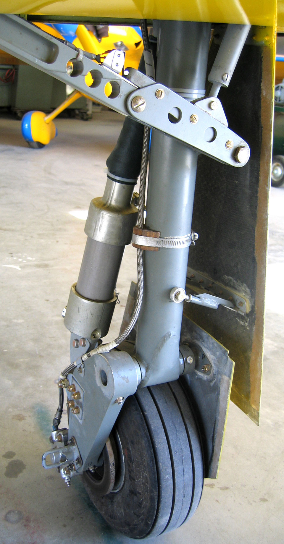
Ralph’s design demanded a unique approach regarding the retractable tricycle landing gear. A superb scrounger, Ralph acquired a nose gear assembly built by Air-Right Mfg. The nose gear was originally designed for the Swearingen SX-300 and is steerable via the rudder pedals.
The main gear was entirely designed and built by Ralph. They are a trailing-arm design and feature 4.5 inches of damped travel. Landings are nice and soft, with very little energy transfer to the airframe. The down tubes were constructed of 2.5-inch-diameter, 4130 “Chrome-Moly” steel tubing with .095-inch thick wall. Axles and pivots were machined from 4130 steel as well. The trailing arm was machined from 2024-T3 aluminum. To finish out the mains, Ralph chose Cleveland brakes and 5.00x5 tires.
The hydraulic shock absorbers are a study in innovation. Ralph acquired speed brake actuators from a North American-built F-86 Sabre of late-1940s vintage. He drilled a series of oil-metering holes in the piston assembly to provide damping. He filled his new shock absorbers with Mil Spec 5606 hydraulic oil and pressurized them to 1400 psi with nitrogen. To keep dirt off the rod and seal, he fabbed flexible boots. And voila—DIY oleo shocks!
To retract the main gear, he decided that hydraulics would get the job done and calculated the forces involved to pull the mains into the wing’s gear wells. Again, he went to the “bone yard” and salvaged two F-86 nose-gear door actuators that were correctly sized for the job. Ralph also used the F-86’s 24-volt hydraulic power pack, which provides 1200 psi (83 bar) to retract the gear. A Cessna 210 gear switch assembly was used to control the gear’s operation. Micro switches were strategically placed to monitor gear position and provide the “three-green” indication we all like to see prior to a landing. Gear extension and retraction time is approximately five seconds each way. The wing and landing gear fabrication took just over two years to complete.
The canopy really gives the GT-400 its fighter-like feel and provides superb visibility. It hinges on the right and latches on the left side. Sailplane canopy maker Gordon Olsen fabricated the GT-400 canopy for Ralph. No plug was used, as Gordon prefers a “free” vacuum pull using only templates as guides. Five pulls were conducted and minor adjustments to the system were made before Gordon was happy with the canopy quality. Plexiglas with a pre-form thickness of 1/4 inch was used. The optics are great; there is virtually no distortion. Additionally, Ralph made a carbon-fiber canopy frame that ensures canopy rigidity under all flight conditions.
Instrument Panel
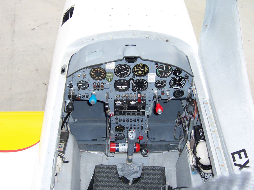
One look at Ralph’s three-piece instrument panel and there is no mistaking his military roots. The left panel is home to the push/pull throttle and constant-speed prop control. Electric rudder trim is positioned on the lower left and the gear lever is on the lower right. Just above are the gear position lights. A 300 mph airspeed indicator is in perfect position for viewing, with a “g” meter mounted just to its left. Ralph also controls the hydraulic pump and cabin heat on this side.
The magnetic compass sits at the top of the center panel. Just below is an array of gauges: an altimeter, rate-of climb indicator, and electric turn coordinator. Curiously, sitting in the upper left position is yet another airspeed indicator. Ralph converted this unit to an angle-of-attack sensor. He plumbed it to orifices on the leading edge of the wing to sense the airflow differential around the wing. When the needle swings up toward a low speed number, he knows that the wing is ready to quit flying. Also located on the center panel are avionics and boost pump switches, as well as a NARCO 195B radio and transponder. Below the radio stack, circuit breakers are conveniently placed within easy reach. The center panel concludes with pressure and volt gauges and a removable fire extinguisher.
The right panel contains all the engine-health monitoring gauges such as EGT, CHT, oil pressure, and oil temps. Ralph put the mixture control here so the he can monitor and adjust exhaust gas temperature. Finishing out the right side panel is the fuel gauge and cowl flap lever.
When the mechanical flaps were converted to hydraulics, Ralph installed a flap up/down selector valve that sits below the mixture control on the right panel. To extend the flaps, he selects the “down position” and strokes the flap pump handle located on the right side of the cockpit by his leg. Each stroke extends the fowler flaps about 5 degrees. Total extension is 30 degrees and it takes less time to extend or retract the flaps than your average Cessna electric flap system. A center-mounted control stick rises from the floor. Push buttons are mounted in the grip for up/down elevator trim and a radio transmit button.
Engine and Prop
In typical cost-cutting fashion, Ralph did not just buy any off-the-shelf engine. That would have been easy, but boring. Instead, he harvested a 6-cylinder, Continental IO-520-F from an Israeli Cessna 206. The logbooks were in Hebrew and Ralph translated them enough to ascertain that the mothballed engine was more than 50 percent to TBO. Ralph thoroughly cleaned the engine and borescoped the cylinders to assess their condition. Additionally, he replaced all the rubber seals and inspected the magnetos and fuel injection system. The engine ran fine upon its first startup. It produces 300 hp (285 continuous) at 2800 rpm.
In search of a prop for the speed range that the GT-400 would be operating in, Ralph looked to twin-engine aircraft and liberated a three-blade McCauley from a Cessna 310. The 78-inch-diameter, constant-speed prop was a bolt-on for the Continental, and is a full feathering design but is modified to limit the pitch travel to full pitch for normal flight. He capped it off with a 14-inch aluminum spinner.
Performance
The GT-400 was designed to be an easy flier. It is roomy, with plenty of leg and shoulder room. Headroom is tight, however, for anyone taller than 6 feet. There are full harnesses for pilot and passenger. The passenger has a control stick, rudder, and throttle, but no brakes. No other controls are available in the back seat. A triangulated roll bar separates pilot and passenger. The canopy has a mechanism that latches it in three places on the left side of the fuselage rail.
The Continental starts easily after the boost pump-primer dance. With his left hand on the throttle, a simple push button on the right side of the panel cranks the starter. After warm-up and checklist completion, Ralph heads out to the runway. He pumps in 10 degrees of takeoff flaps. Due to the high wing loading, the GT-400 will use up to 2,000 feet of runway. With 300 hp available, the prop produces 1,100 pounds of static thrust; as the GT-400 rolls down the runway, he accelerates to 100 mph and rotates off the deck. Ralph points the nose upward and accelerates to 150 mph, climbing out at a conservative 1,000 feet per minute.
Until additional flutter analysis is completed, Ralph has a self-imposed VNE of 200 mph during the initial flight test program, but knows the GT-400 has some more speed in it. “I designed it to cruise at 260 and top out at around 300 mph. We will just have to see how it goes,” he said.
After 10 years, 10,000 building hours, and $40,000 invested, Ralph Wise is the epitome of persistence. He was not afraid to design from scratch, scrounge parts, and learn new building methods. Ralph tested new ideas and made changes when needed. The result is a design that few can match.
My only question to Ralph is, “When can I get one of my own?”
GT-400 Specifications
Length 21 feet
Wing Span 24 feet
Wing Area 85 square feet
Wing Loading 30.5 psf (@2,600 pounds)
Empty Weight 1,858 pounds
Gross Weight 2,600 pounds
E. Flat Plate Area 1.5 square feet*
Airfoil NACA 63-212
Rate of Climb 1,000 fpm
Top Speed 200 mph (so far)
Engine Continental IO-520-F
Horsepower 300 hp at 2800 rpm
Propeller 78-inch McCauley three-blade, constant speed
* Estimated
