Setting or Driving Solid Rivets
By Jack Dueck, Chairman, EAA Canadian Council, EAA 337912
September 2015 - The objective of a riveted connection can be broadly stated as, “a connection, held by properly driven rivets that maximizes the strength and enhances the appearance of the joint.” You will note two noteworthy components in this sentence—“maximizes strength” and “enhances appearance.” These two conditions are not mutually exclusive, because if one condition is met, the other usually follows as well.
Here is what you want to achieve in the finished joint:
- Material pieces clamped firmly together
- No deformation of material
- Rivet shop head concentrically deformed about its original axis
- Rivet shop head deformed to correct tolerances
Difficulties
Rivet-setting pressures are high. If you consider that deformation must occur at a value above the yield strength of the rivet, you can calculate that the setting force of a -3 (3/32-inch diameter) rivet is in the order of 345 pounds and of a -4 (1/8-inch diameter) rivet, 615 pounds. This axial force must be applied to the rivet in order to mushroom the shop head concentrically. Any nonaxial force vector will tend to bend rather than expand the rivet.
That’s the first concern.
Next, the individual material pieces need to be firmly clamped together during this setting process so that no intermediate space allows the rivet to swell between the materials.
Finally, the components cannot be allowed to move relative to each other during the setting, or the rivet or the forces applied to the rivet will tend to deform the material and not the rivet.
Riveting Tools
Two riveting procedures have evolved. The rivet squeezer is a compression type of tool that applies a continuous axial force to the rivet, deforming the shop head. The rivet gun is an impact type of a tool that provides repeated axial impact forces (think hammer) to deform and set the rivet.
To use the rivet squeezer, the correct rivet die (universal or flush) is installed on the factory side of the rivet squeezer, and an anvil (or flush) die is installed on the shop head side of the squeezer (Figure 1).
The material pieces are firmly clamped together and also firmly clamped to a workbench or jig, and the squeezer is operated smoothly and axially to the rivet to set or deform the shop head. It is very important to begin the squeezing operation with the rivet factory head as tight to the material as possible, allowing the setting to take place at the shop head of the rivet (Figure 2).
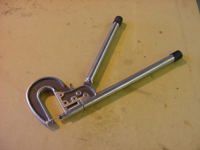
FIGURE 1
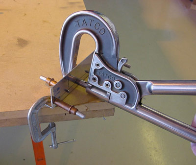
FIGURE 2
Rivet squeezers come in a variety of types. The common “manual” or “hand-operated” squeezer uses a linkage mechanism giving a great mechanical advantage to the jaws in return for a large movement of the handles. This squeezer is useful for -3 rivets and can also be used for -4 rivets, but most people will find the large hand forces for a -4 rivet are difficult to achieve. A variation of the hand squeezer uses a compound action that increases forces to the rivet as the squeezing motion reaches the latter part of its travel, allowing the setting of a -4 rivet with relative ease.
“Pneumatic” rivet squeezers (Figure 3) are similar to hand squeezers but rely on a pneumatic air cylinder to provide the forces required to set the rivet.
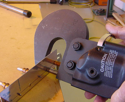
FIGURE 3
As stated, the rivet gun employs an impact force to set the rivet. To use the rivet gun, the appropriate set (Figure 4) is installed into the gun and safetied with a retaining spring. The set is then held to the factory head and the rivet is driven by a series of impact blows from the gun against a restraining bucking bar held against the shop head of the rivet. Both the rivet gun and the bucking bar must be held so as to ensure that the impact forces are axially applied to the rivet (Figure 5).
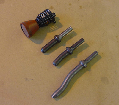
FIGURE 4
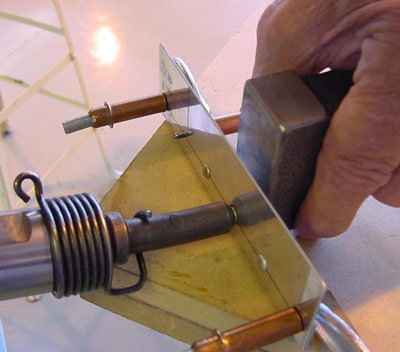
FIGURE 5
Since the impact forces are applied to the factory head of the rivet, it is imperative that the rivet gun and set not be allowed to come off contact with the rivet. Allowing the set to “come away” from the rivet during successive drives will guarantee distortion of either the rivet, the material, or both. For this reason the rivet gun method should be considered a two-person operation; one operating the gun and the other holding the bucking bar.
Again, it is very important that the operation begins with the rivet set holding the factory head tightly to the material and that the bucking bar pressure on the rivet be increased as the rivet is set.
The strength of the impact of the rivet gun is controlled by: 1. Adjustment of the air regulator on the air supply to the gun, and 2. By tickling the trigger action on the gun. A good gun will allow you to control small tap, tap, taps, with a small trigger deflection, and then you can increase the impact by further increases on the trigger pressure. I find that if I can begin setting the rivet (ensuring all the conditions are met) with a few initial light taps, then the rest of the process is readily achieved. Avoid overdriving the rivet on initial taps.
A signal system must be derived between the gun operator and the person holding the bucking bar. (See tapping code in Figure 6.)
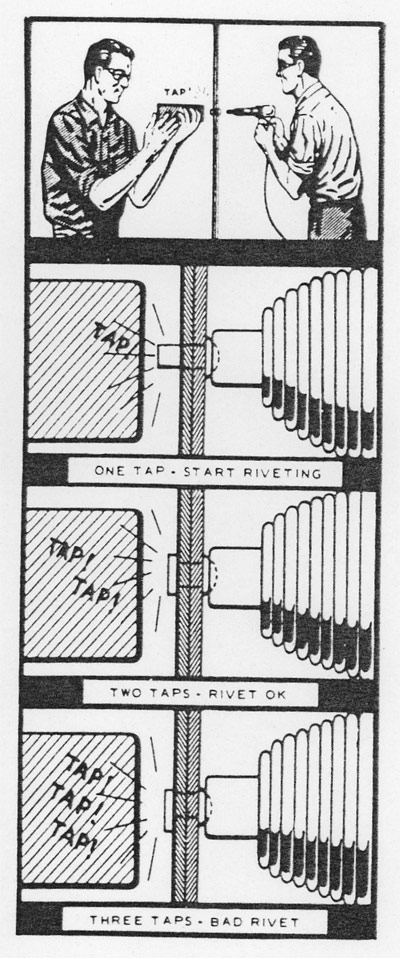
FIGURE 6
Back-Riveting
You will note that in the above description of setting rivets with a rivet gun, the impact of the rivet gun set was always directed at the factory head of the rivet. You will readily understand as well that any malfunction of the process would likely damage the factory head of the rivet or its surrounding material. The back-riveting process reverses this procedure. The rivet gun set is now applied to the shop head of the rivet, and the factory head is supported on a steel plate (Figure 7) or a bucking bar. Normally this would apply to flush (AN426) rivets, but universal head (AN470) rivets can also be driven in this manner by drilling a hole into the back plate and inserting the correct universal head die into this hole. Make sure that the rivet is correctly centered on the die before driving it. This allows much more confidence in achieving an aesthetically pleasing surface to your project.
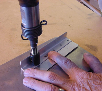
FIGURE 7
Which Method to Use
Your choice of setting your solid rivets will depend on your confidence with each of the above methods. In many cases the choice or method will be decided for you by the physical restrictions or conditions of the joint. My choice, if possible, would be the one that gives me the most control of the desired objectives stated above. Therefore in my world my choice would follow this hierarchy:
- Pneumatic squeezer
- Hand squeezer
- Back-riveting with rivet gun set against the shop head of the rivet
- Rivet gun with set against the factory head of the rivet
With patience and practice, all of the above methods will give excellent results. Using the rivet gun to set rivets is the most demanding of all. A constructive strategy is to lay out 20 rivet holes in scrap materials and drive these 20 rivets each day for 10 days. This simple exercise will produce the level of confidence needed to proceed with your project.
Defective Rivets
Defective rivets need to be replaced. Defective rivets will result from:
- Improper diameter and/or length of the rivet. Remember that material distortion is likely if the rivet diameter is more than 5.5 times the thinnest material of the joint. The length of the rivet is very important. The rivet length protruding through the joint should be 1.5 times the rivet diameter. When the rivet has been set, the shop head should have a diameter of 1.5 the original rivet diameter, and its depth should be at least .5 times the rivet diameter. (See Figure 8).
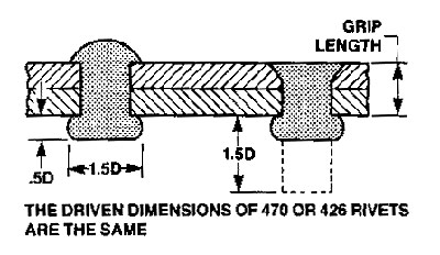
FIGURE 8
- Rivet “dumped.” If the rivet length protruding through the material of the joint is more than 1.5 times its diameter, and especially if the setting forces are not perfectly axial, the rivet shank will tend to bend over rather than deform concentrically.
- Rivet driven at a slant. If the forces applied to the rivet during setting are not axial the material pieces of the joint will tend to move relative to each other.
- Space between materials of the joint. Clamping forces must be applied to the joint during the setting process. Any space between joint materials will allow a swelling to occur in the rivet at this location, and the joint will lose its frictional shear component of the joint strength.
- Damaged rivet head or material due to the rivet gun set being allowed to “come-away” from the rivet during the setting process.
- Rivet cracks from material hardening. Rivets of the AD category should be driven within two to three seconds. As these rivets are driven, the material hardens. If rivet cracks are visible, the strength of the joint is compromised.
Inspecting Driven Rivets
As stated before, every rivet is a challenge and deserving of an inspection to affirm its suitability. As well as inspecting for the above defects, you will want to know if it meets the size tolerance criteria of item 1 above. You should build a simple gauge (Figure 9) that allows quick and easy confirmation of the correct setting dimensions.
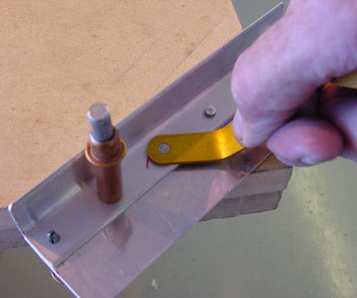
FIGURE 9
Consider a -4 rivet (i.e., 1/8-inch diameter). The set shop head should be 1.5 times the diameter or 3/16 inch, and its height should be 0.5 times the diameter or 1/16 inch. Figure 9 shows a simple gauge with a #11 drill hole (slightly larger than 3/16 inch) and a thickness of 1/16 inch (or 0.063 inch) that will give you the required parameters. This hole should just fit over the set rivet, and the height of the rivet should be about equal to the thickness of the gauge material. Likewise for a -3 (3/32-inch diameter) rivet, the gauge hole should be about 0.144 inch or #27 drill, and the thickness should be about 0.050 inch.
Removing Defective Rivets
To remove a defective rivet, follow these steps:
- Drill a hole (same size as the original) into the head of the rivet, using the rivet dimple to help locate the center. Drill only through the head (either universal or flush).
- Insert a pin punch into the hole and pry off the head.
- Support the material on the back side, and using the pin punch drive the remaining rivet shank out.
- Replace the rivet with the same size and type of the original rivet, provided that the hole has not been enlarged.
I find that his works about 50 percent of the time. If there has been any swelling of the rivet between the materials of the joint, or if the hole has not been drilled precisely in the centre of the rivet, this will just not happen. And the only solution is to drill right through the rivet and contend with a larger hole.
Oversize Rivets
Oversize shank rivets (NAS1097AD-4) rivets are available with a head size the same as the AN426-AD-3 but with a shank diameter of 1/8 inch. If the hole becomes too big, redrill it with a #30 drill and install one of these “oops” rivets.
Soft Rivets
In instances where metal materials such as aluminum or steel and fiberglass are joined by rivets, the setting forces of the AD rivets (tensile strength of 36,000 psi) will tend to crush the fiberglass. The softer category “A” rivets (tensile strength of 16,000 psi) will help alleviate this concern. (AN426A and AN470A.)
This completes our look at setting (or driving) solid rivets. Our next column will consider the use of blind rivets in the construction of amateur-built aircraft.
You can read about an interesting experiment to test the strength of rivets set well and not so well in an article written by Bill Marvel here.
Ref: Standard Aircraft Handbook, Larry Reithmaier, McGraw Hill
Sheet Metal Basics, EAA SportAir Workshops, EAA
