Hoerner Wingtips Part 7 - Loose Ends
By Bill Evans, EAA Chapter 266, EAA 794228
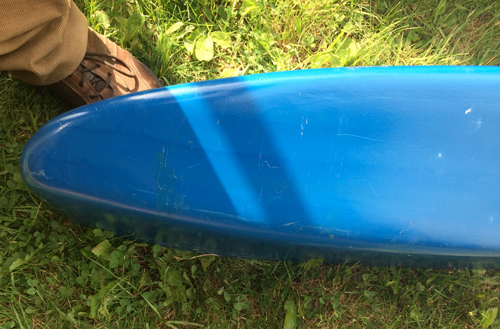
Fitting Wingtips to the Wings
You may recall the wingtips being installed over 0.032-inch AL strips which allow for a small amount of error in the wingtip profile. The foam templates were made 1/16 inch larger with these strips in mind. It turns out that if you Fiberglas in the bulkheads right away, the Horner wingtips will install nicely.
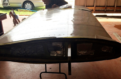
If, however, you complete one and leave the other, the epoxy resin and polyester filler cure differently such that the wingtip will distort as it fully cures. When it came time to finish the second wingtip, the upper surface was found to be slightly convex and had to be heated and clamped onto additional cross-form wood templates to remove the distortion. If this was to be done again, obviously we’d change our work sequence or leave the second wingtip on the foam plug or even remove it, cut up the plug into slices and reposition them to eliminate distortion. Storing the wingtip shell empty for a month apparently was not a good choice.
Outboard rib
As we write this now, heating and clamping the wingtip after it has stood for a while works well for the epoxy resin, since it softens and can be reformed as many times as you wish. The cured polyester filler, on the other hand, gets warm, and even hot, but does not soften in the way that epoxy does. When you install the 12-inch machinists “C” clamps, the wingtip changes shape, but the filler cracks and those cracks open. “Ugly” is the word that comes to mind.
Cracks in filler
Now the polyester filler we used is very expensive stuff and it works wonderfully. With a fingernail, you can tell exactly the moment it starts to harden enough to use the shear and then sander to finish it. The filler also changes colour. When the hardener is mixed in, the filler becomes slightly blue, sky blue, in colour. As it cures, it turns white again. You can use the colour as a guide to finishing. To our knowledge no such epoxy filler has the same properties: lightweight, speed of curing, and great workability. Any number of primers adhere to it well. If a similar epoxy filler does exist, I expect it to be outside our total budget of $500.
Thus the decision to use this filler remains the best decision, but the process needs to be revised. Possibly it might be a choice to install the completed wingtips unfilled, and therefore unpainted. That would mean turning the whole wing for each step of the finishing process. You’d need an extra pair of hands for that.
This brings us to the second loose end. The wingtip chord section is a fraction too large to fit the wing perfectly. The wingtip flexes some and the aluminum strips flex a little, but if you installed the wingtips unfilled etc., then heat (from a 1,800-watt hair dryer) would soften the resin so that you could use leftover aluminum strips to draw the flanges in to meet the aluminum strips perfectly. There would be no filler to crack.
Alternatively, you could heat-fit the unfinished wingtips in this manner, allow the resin to reharden, then remove the wingtips for filling and painting. That just might be the best choice, since it does not compromise the fit and allows for easy access during filling/finishing.
Fuel Transfer
The tip-tanks are lower than either of the fuel tanks in the fuselage. Possibly you could install a fuel valve such that fuel could flow from the tip-tanks to the carb. I don’t intend to do that, because once one tank is empty, air would be introduced into the fuel system. (One could not count the numbers of engine power-loss incidents due to fuel starvation, however caused.)
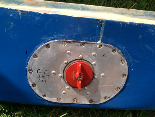
Fuel cap
There will be a Facet fuel pump fed by a tee fitting supplied from both tip-tanks. The plan is to plumb it into the outlet line to the auxiliary or cruise tank. Selecting the fuel pump switch “up” turns on the fuel boost pump. Switching it “down” turns on the transfer pump from the tip-tanks. This model of transfer pump has an internal pressure check valve. If the pump is on, the diaphragm valve at the outlet is opened by fuel pressure. Once it is switched off, the check-valve closes by spring pressure, preventing fuel from draining back from the aux tank to the tip-tanks. The auxiliary tank holds, say, 10 imperial gallons, so the 7-gallon tip-tank capacity would not overfill the auxiliary tank. The checklist for fuel transfer will be to select “fuel feed” from the main tank with the fuel boost pump on. Once feed is assured (one minute), select the transfer pump “on” to fill the auxiliary tank. Once filling is completed, select the pump switch to “boost,” then select the auxiliary tank. After one minute, the boost pump may be switched off.
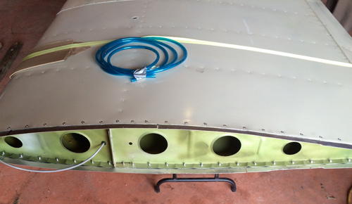
Wing root
The lines and fittings chosen therefore are 1/4 inch, which is adequate since there is no intention of feeding the engine from the tip-tanks. Thus whether the fuel transfer takes five minutes or 15 is a moot point.
Suppose there was air in the fuel line after transfer. Would it cause fuel starvation?
No, the facet pump would maintain, say, 3 psi in the system and force air/vapour out of the lines into the float bowl of the Bing 40 mm carb, where it would be vented to the inlet throat of the carburetor. The fuel passages remain free of air. Why? The carb float does not recognize either air or fuel vapour, so the fuel level remains constant in the float bowl.
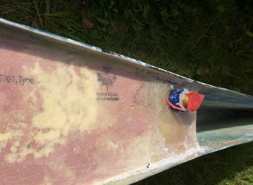
Fuel fitting
Strobe Lights
Wingtip strobe lights are a bit tricky to locate. The airworthiness manual and perhaps the amateur-build chapters stipulate the angles at which strobes and nav lights should be visible. Also, there is the question of security. Strobes mounted at the wingtip are vulnerable to breakage or other damage of every sort. In our case we took advantage of the Hoerner bevelled shape to protect the strobe lights, as some of them cost hundreds each. You can see from the photo that the strobes would neither touch any vertical object in contact with the wingtip nor anything hitting the leading edge. Combining the two: damage protection and strobe visibility is the trick.
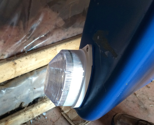
Strobe location
Aileron Balancing
Some readers may have noticed that the promised section on aileron balance weights moved to be faired with the wingtip has not been written yet. Our plate has been full enough that it’s been decided to leave the ailerons as they are and redesign and relocate the balance weights after the plane has been test-flown.
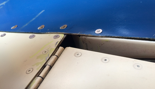
Wingtip trailing edge
Every system related to the J300 engine has been modified to suit the conversion. There are, say, 10 of these subsystems. It may well be wise to leave the flight controls alone, until after flight-testing is completed.
