Sonerai Engine Conversion to Jabiru 3300, Solid Lifter Engine
From Bits & Pieces Newsletter, March 2015 Issue
By Bill Evans, EAA Chapter 266, EAA 794228
One of the challenges of final assembly in an engine compartment is that you need to start in the center and progressively install components toward the periphery. In my case, once the bits are in, it looks like a small jungle. Well, that’s relative. It’s nothing like the Rotax 982, which needs to be studied to be believed.
Months ago we had a 304 stainless steel box welded up for the air filter – stainless steel because it sits aft of the firewall. Thanks to Marc Clement of Aerosoudage Industries for the welding.
Because it vibrates, the engine must have a flexible connection to the air-box. Usually this is done with scat hose. That won’t work here, because for CG reasons the carburetor inlet is right at the firewall. What is to be done to provide a firewall?
The original engine was positioned much further forward, such that the air-box sat behind the aft accessory case on the firewall. As we shall see, that doesn’t work with the longer, heavier Jabiru 3300 engine. The air-box photo shows installation aft of the firewall.
Stainless-steel air-box during installation
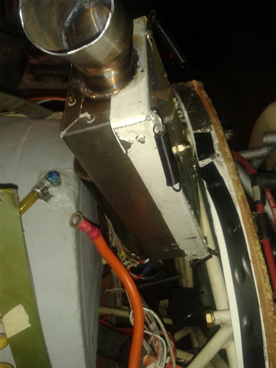
Today we fabricated spring clips, cut NAS clamp bolts to length, installed clip nuts on the box, applied Permatex sealant to the lid, and got it together before the sealant cured. The sealant is separated from the box by plastic wrap, which comes off before final installation.
The four cover bolts also attach the spring clips. One cannot bolt a filter box to structure unless there is a minimum length of air hose in between. Our solution is to install aircraft cushion clamps - the ones with the rubber covering - to the fuselage 4130 tubing and then install coil springs between the four spring clips (above) and the four tube clamps. These steps both retain the air-box and allow for engine vibration without breaking things or pulling the rubber couplings off the carburetor. The carburetor is a 40-millimeter Bing, which I worked on previously.
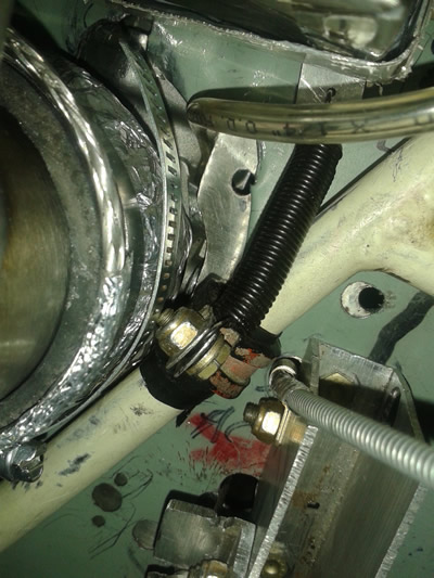
Once the carburetor and air-box are in, then a braided SS fire shield needs to be fabricated in halves and clamped to the coupling. It must be capable of a little movement as well.
Braided coupling
Some of you may remember that the 32-millimeter carburetor for the previously installed Jabiru 2200 needed special linkage to fit the Sonerai aircraft. Sonerais are typically built with a lever or quadrant type of throttle rather than a push-pull knob. The quadrant reverses the travel for the original VW Revmaster engine, which I have never owned. On the 32-millimeter Bing, you have a choice of sides for the throttle lever.
However, the 40-millimeter Bing for our Jabiru 3300 has an electric carb heat element bolted to the carb body right where the butterfly is – on the left side. These may be obtained from Jabiru USA. Thus the throttle must go on the right side. The trouble is that when the throttle is advanced, the butterfly closes and vice versa. We won’t have an aircraft like that, though apparently Willy Messerschmitt built them that way: Pull the lever aft to open the throttle.
What to do? It turns out that the throttle and the idle adjustment plate are both designed so that they may be installed with the throttle lever pointing either up or down. The throttle lever is a very tight fit, but carburetors are delicate. Thus it takes some thought and patience to remove the throttle lever and idle plate, invert them, and put everything back together.
We called Gord Larsen of Jabiru Canada just to be sure there were no surprises in store for us. I hasten to add that while the throttle lever comes off the butterfly shaft, you must not remove the butterfly, shaft, etc., and invert them. That effectively turns the carburetor upside down. It also defeats the fuel-starting mechanism. For what it’s worth, don’t do that!
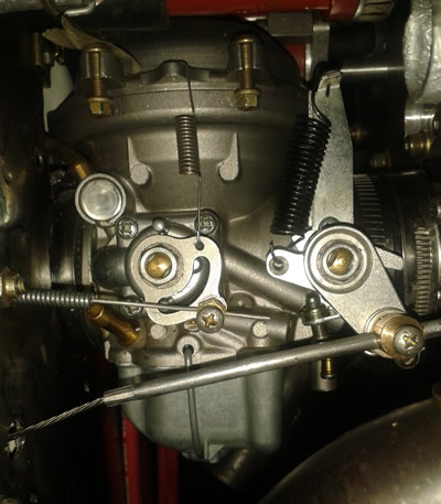
Control on right is throttle; choke on left.
The other thing you should know about engine controls is that all the controls and their sheathing or tubing must be retained by bare steel clamps. (See braided coupling above.) Over time, heat and oil will deteriorate neoprene. If you use rubber-cushioned clamps, one day the sheathing will move and the control will not. Heed Murphy’s Law here and use steel clamps.
Next, we will finalize the air-box, then install it onto the carburetor. Once these two are installed, the control cables can be routed, connected, and safetied.
The 40-millimeter Bing carb comes with two exterior coil springs. The smaller spring pulls the fuel choke lever to off. The spring seems to suit our application since it does not significantly add to the choke knob forces required to start the engine. If the choke mechanism broke, the choke would be pulled “off” by that spring. The throttle would move to full throttle.
Note: Unless you invent one, the 40-millimeter Bing carb does not have a fuel shutoff at the carburetor. The only fuel shutoff is a valve at the firewall. Therefore, for both start and shutdown, you want to have the throttle butterfly close completely – shutdown because you want the slowest possible idle when the mags are switched off, and starting because even in warm weather you need extra fuel for starting.
The choke is not a butterfly; it is an internal fuel valve with fuel passages, described as the choke fuel circuit. When the choke is selected “on”, this valve is opened. Provided that the throttle butterfly is closed tight, engine vacuum will draw the needed fuel through the fuel starting passages into the manifold for starting. After starting, maybe 30 seconds later the choke valve may be progressively closed. Even though idle may be 450 rpm, our engine will both start on the first blade and idle at the aforementioned 450 rpm. You won’t get it to idle much below that because the engine needs to crank at 300 rpm to start. Note: The battery needs to be healthy for takeoff. If the engine stopped due to throttle at idle, you need the starter and hence the battery.
In cold weather, you need more blades of hand propping to get enough fuel for starting. It took us maybe a year to get this down to what renowned test pilot Alex Henshaw might call “a nicety”.
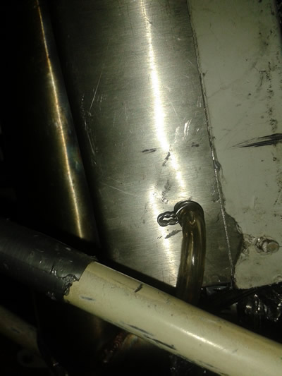
The air-box we are discussing here is a required sense pressure for the 40-millimeter Bing carb. (See photo below.) Bing carbs are pretty much all constant-depression carburetors. That means that the speed of the air passing through the carburetor is constant. Simply said, there is a large sealed diaphragm, which senses the difference between throat air pressure (Pt) and the air pressure inside the air-box (Pa).
The air-box port needs to be at a location above the air filter but where the airflow is relatively static. The difference (Pa – Pt) between these pressures controls the position of the carburetor throat piston, which contains the intermediate needle valve. The carburetor is connected via a sense line to the air-box port. If this is not done correctly, the carburetor will not operate and the engine will not run, certainly not well.
Carburetor sense port
Why bother? The constant-depression carburetors essentially do not have a venturi, which means that carb icing is very rare. I’ve never experienced it in seven years. It also means that the carburetor has some ability to compensate for altitude change. The model of carb we have operates normally to 18,000 feet. Neither does it need a mixture control. The needle valve controls the mixture in the middle power band. It took us a while to get our minds around the constant depression concept, but once understood, it works very well and has been reliable for us.
The intake air comprises a larger 2-½-inch NACA duct in the lower cowling, which feeds a 2-½-inch scat hose through a right-side blister fairing past the firewall, then back into the forward fuselage via a 2-½-inch flex SS duct, which leads into the air-box. Thus in the forward fuselage the air intake is all shielded by stainless steel of several forms. In the event of an engine backfire, the cockpit is both protected and sealed against fire.
We’ve never known properly set-up Jabiru engines to backfire. If the spark plug leads are correctly installed, these engines tick like a clock. Even so, a stainless engine firewall is a must – whatever needs to be done to achieve that.
