Last month we described an experiment to determine ways to maximize the strength of a weld involving 4130 chromoly tubing. The research questions addressed in this study were grouped into three general categories of process, filler, and post-weld heat treatment.
For the welding process, we wanted to determine which process is the best. We wanted to determine whether there are significant differences in the part performance from different welding processes. We also wanted to consider which process would be easiest for an amateur welder to use with success. When considering which fi ller material is the best, we wanted to see if there were significant differences in part performance with different fillers, as well as what filler material would be easiest for an amateur to use. Next we looked at pre- and postweld heat treatment.
We wanted to know if pre-heat is required or if post-weld heat treatment is required. If so, we wanted to know how much was required and for how long. The bottom line is whether pre- or post-weld heat would create a difference in the final weldment. We carried out a program of testing under controlled conditions. No attempt was made to compare the results of using flat specimens to tube-type connections. The outcomes are intended as a base line reference to further the work in tube connections, but the base line of materials, processes, and filler metals needs to be conducted to examine interactions of the three primary variables. Further considerations included stress-relieved and non-stress-relieved test coupons to determine the effectiveness of the process.
How the Study Worked
This study is limited to the testing of 4130 steel in the flat position, with the process and filler metals listed. Test specimens were prepared and welded by certified personnel under the prescribed conditions. Test specimens from the same group of weldments were alternately stress-relieved and not stress-relieved to examine the effectiveness of the post-weld heat treatment.
Tests were conducted on certificated machines in a manner consistent with industry practice. No other thicknesses of material were tested other than .050-inch material. The samples were prepared and tested for hardness in the base metal, in the heat-affected zone, in the weld metal, in the heat-affected zone on the other side, and lastly in the unaffected base, as shown in Figure 1.
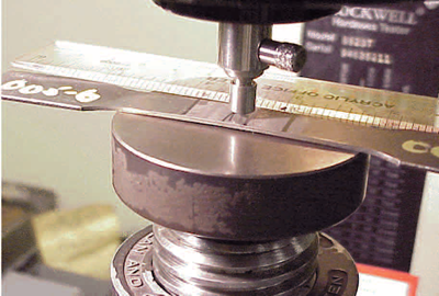
The hardness test that was used was the Rockwell hardness test on the “A” scale. Hardness and tensile strengths are relational, and so it is possible to draw some estimates about tensile strengths from the hardness values. Hardness and brittleness are also loosely correlated to each other in that as hardness increases so does brittleness. Brittle failures in welds are fast-opening displacements with little warning of failure until fracture has occurred. The test coupons used in the project were prepared as follows. After the materials were procured, we sheared the coupons and machined the sheared edges. The coupons were pre-cleaned.
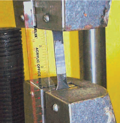
We then welded the coupons and stress-relieved the selected coupons. After welding them, we visually inspected the welds, photographed the coupons, and began the testing regimen. The tensile specimens that were pulled were pulled transverse to the weld in what is known as a fl at bar specimen as shown in Figure 2. The tensile strength was then calculated by dividing the load in pounds by the area of the specimen in square inches, thus the final units of pounds of loading per square inch, or PSI.
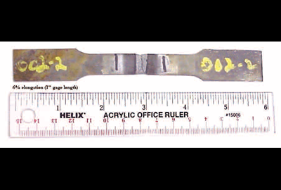
Lastly, the tensile specimens once broken were measured to see how much they stretched or elongated before they fractured or broke. This was done by using a gauge length of 1 inch and then measuring the final gauge length when the tensile is complete as shown in Figure 3, expressed as percentage elongation.
The program of testing was carried out under controlled conditions. No attempt was made to compare the results of using fl at specimens to tube-type connections.
The outcomes are intended as a base line reference to further the work in tube connections, but the base line of materials, processes, and filler metals needs to be conducted to examine interactions of the three primary variables. Further considerations included examining whether stress-relieving the coupons was a useful and effective process. It should be noted that the tests used for the coupon evaluation are relative in and unto the specimens themselves only. First, hardness tests are relative to the material and the weld being tested. When testing the weld, it should be acknowledged that the weld metal does not generally yield, as does the base.
So discussing yield of the tensile coupons and elongation is not relevant for the comparison of base metal tensile and elongation in the final weldment. There is no best method of welding. All of the processes tested could be used to weld chromoly for the tests as conducted. Certain processes are easier to learn, some are more forgiving, others are cleaner, and still others are more advanced technically.
We do not consider any one method “best” because the best weld is often the result of a process you already own, or the process that you already are profi cient at. If there is a preferred combination to be put forward for consideration, it would be to use TIG welding with a power source that exhibited a stable and smooth arc that would “light off” at low amperages with a small diameter tungsten and that would be user friendly to set up. The torch body would be small and fl exible with light cables and small diameter gas nozzles, so the welder could manipulate the arc and see the puddle.
Lastly, the filler would be easy to manipulate and flow into the puddle with a quiet addition into the puddle so that the integration of base and filler had little or no turbulence.
Recommendations
For filler metal, we found the hand-fed processes of GTAW (TIG) and OFW (gas welding) were most compatible with the filler ER-80-SD2. ER-80-S-D2 developed strengths approaching that of the base metal, with a minimum amount of turbulence as the molten filler entered the arc. RG-45 and the RG-60 produced welds that fell outside the parameters of acceptability for welding on 4130.
The RG series of filler materials lack the strength to be compatible with the base material. For processes, as mentioned above, we found that any of the processes could be used to weld 4130. However, there are certain processes that could be construed as having preferred characteristics.
One of the desires of welding is that the base and filler metal combinations “match” so that minute amounts of the base material are thermally affected. All of the processes produced acceptable welds for the applications of amateur aircraft building.
When we looked at post-weld heat treatment, we found that it did make a difference in the controlled experiment as conducted. However, in practice the oxy fuel rosebud heating tip—or worse yet a cutting torch—is many times employed as the heating source. These may or may not be adjusted to a neutral flame, and the heat may or may not be applied evenly. That means they may or may not produce the desired reduction in hardness and the increase in toughness and ductility.
As an aside, consider that all metallurgical reactions are dependent on time and temperature. The complex carbides that form in chromoly steels are difficult to disassociate and dissolve. If there were only an average four-point reduction in hardness in 25 minutes at 1,025°F, it is doubtful that oxy fuel will have a significant affect in the 5-7 minutes that it takes to heat the joint to a dull cherry red.
In the end, it’s your project with your body strapped into it, whether it’s a plane, roll cage, or a glider. Practice welding before you begin the project. Develop welding procedure specifications like the ones in this article. You could even consider having an AWS certified welding inspector look at your welds or have an independent testing lab destructively test some of your best practice welds. It’s up to you to decide how you will demonstrate that you are qualified to produce the welds in your project. It’s also up to you to make sure you can reliably produce welds that make your project as safe as it can be.
