Push-Pull Tube Control Installations
By Tony Bingelis (originally published in EAA Sport Aviation, November 1981)
FIRST, LET ME set the record straight on one thing in the matter of push-pull control systems vs. cable control systems. Some very authoritative books and manuals state in absolute terms that the main disadvantage of using cables for control linkages is that their tension must be adjusted frequently due to stretching and temperature changes. This simply is not so . . . not in small sport aircraft.
I guess some expert, many years ago through logical reasoning, figured that such tension changes must take place in cables and duly recorded his conclusions as fact for posterity. In the years to follow, one writer after another perpetuated that same spiel as gospel.
However, I happen to have a personal acquaintance with one 14 year old homebuilt aircraft that has not had its control cables adjusted in all those years . . . nor has the need ever arisen. Another aircraft several years its junior likewise seems to defy the need for "frequent (or infrequent) adjustment".
Even though cable control systems are without this alleged fault, there are some aircraft designs that are better suited to push-pull control systems. Maybe yours is one of them.
Why Use Push-Pull Control Systems?
It is also said in those ancient tomes just referenced that push-pull tubes eliminate the problem of varying cable tensions (even if the problem is no problem . . . O.K.?). Anyway, one major attribute of a push-pull tube is its capability for transferring control movements through a single link (tube) positively and in direct proportion to the control input.
A single push-pull tube can transfer either tension or compression loads (stresses) whereas a control cable system can only handle tension loads.
It is well to reflect on the fact that, although individual cables are lighter than push-pull tubes, the cable systems, particularly in high wing aircraft, do require the fabrication and installation of many pulleys, brackets and guards. As a consequence, the cable installation tends to become heavier and more complex than you would expect. Additionally, the numerous pulleys and higher cable tensions generally result in a control system that may generate a need for heavy control pressures because of friction. On the other hand, push-pull controls are well known for their ease of movement so characteristic of friction-free push-pull systems.
Where Can You Get Push-Pull Tubes?
Unfortunately, a homebuilder cannot go to one of his local discount stores and shop around for the correct length and size push-pull tubes . . . so, where do you get them? Outside of making them, that is.
Well, since we homebuilders tend to succumb to impulse buying and occasional scrounging, used push-pull tubes immediately come to mind. Where can you find used aircraft materials?
Outside of a lucky find at a builder-friend's shop, aircraft salvage yard, "Country Store or Fly Market" at a major fly-in, your chances of finding used push-pull rods suitable for your need is slim. Still, you may be able to bring home some push-pull tubes with rod ends on them that are exactly what you need except for their lengths.
One problem with most any used salvage or surplus tubes you may locate is that they will probably be very old . . . World War II stuff.
Naturally, there is really nothing wrong with old WWII tubes except that the grease in the rods will undoubtedly have become coagulated years ago and the bearings aren't functioning or they have a lot of drag due to that ungreasy grease in them.
Such bearings will have to be cleaned and rejuvenated (regreased).
Some aircraft supply catalogs list Bearing Regreasers that can do the job. A bearing degreaser is a small inexpensive device with a built-in grease fitting. The gadget is secured to a bearing and the old grease is purged out by forcing new grease through the bearing under pressure from a regular grease gun. Bearing regreasers cost less than most new bearings do. One catch though . . . each size bearing requires a separate size degreaser but they are well worth the few bucks that may be expended.
While it is true that there are still a lot of old World War II vintage push-pull rods and tubes showing up at the Fly Markets and Country Stores, not all of the old push-pull tubes you find will be that old. Due to production and design changes, aircraft companies scrap excess stock that often finds its way into homebuilder supply channels. These push-pull tubes are usually of good quality and are very attractively priced.
On the other hand, be careful to examine each tube closely for elongated or mid-drilled holes, poorly driven rivets, dents and other defects which may have been reason enough for its rejection in the first place.
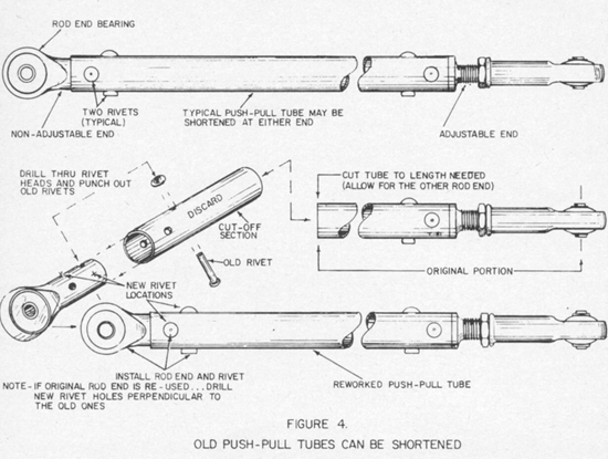
If you cannot locate the exact length salvage tube you need, you could probably cut one down to the correct length. Since only one end has to be modified, this simple rework is an expensive way to get a needed tube. (See Figure 4)
I would point out, however, that it is difficult to impossible for most builders to match drill the rivet holes already drilled through the shank of the rod end fitting salvage from the cut-off end. You could, instead, disregard the existing holes and drill new holes through the tubing and into the rod end shank 90 degrees (perpendicular) to the original holes without weakening the rod end shank. Alternatively, you could install a new rod end terminal to replace the old cut-off one.
Avoid acquiring push-pull tubes with swaged or necked-down diameters on each end unless their length is correct for your purpose (most can be adjusted 1/2"?1"). They are more difficult to refit with a rod end after you have cut off one end that includes the swaged area. The reason, of course, is that you are left with the full diameter of the tubing and the original rod end will be too small for it.
On the other hand, there is no good reason why you couldn't make your own push-pull tubes and rods from new materials. It is a simple matter to select rod ends to fit a particular size of tubing because the catalogs generally provide this information. Incidentally, when assembling push-pull tubes, apply a wet zinc chromate film to the rod end shanks for corrosion protection.
How push-pull Tubes And Rods Are Assembled
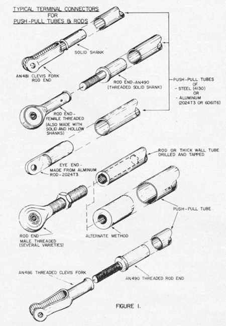
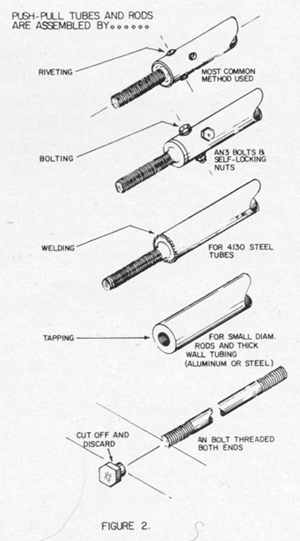
This is covered in Figure 1 and Figure 2.
Riveted Assemblies
Rivets are the most commonly used means for securing rod ends to push-pull tubes. Usually two rivets are inserted perpendicular to each other at each rod end. The rivets must be of aircraft quality (identifiable by the dimple in the rivet heads). Never, ever use commercial rivets in aircraft structural applications! They are too soft and too weak . . . and they are sure to fail you.
Rod ends with hollow shanks require extra care when riveting. That sort of riveting had best be done with a riveting gun as hammering the rivets down against a metal surface (or squeezing them in a vise) may collapse the tubing ends. Of course, rod ends with solid shanks can better stand hand riveting.
Bolted Assemblies
Another push-pull tube assembly method utilizes a couple of AN3 aircraft bolts secured with fiber lock nuts. I personally think bolts make an ugly push-pull tube terminal connection for smaller tubing sizes . . . one that is more apt to catch on some part of the structure and increase the risk of a control jam. Furthermore, a smaller diameter tube assembled with bolts is somewhat heavier than a similar riveted assembly. Naturally, if a large diameter tube is being fabricated you would have no choice but to use AN bolts.
Some production aircraft (and homebuilt T?18s, I believe) use a rather large diameter thin wall tube (2" x .035") for the elevator linkage. Such a thin wall aluminum tube can handle the vibration and bending induced by compression loads and still provide a very light installation.
Welded Assemblies
Welded terminal ends for push-pull tubes are commonly used with steel tubes. The rod end to be welded to the tube should slip into the tube snugly. When ordering your rod ends, be sure they will fit the tubing you must use.
Threaded Rod Assemblies
Threaded rods (male and female) are most effective in shorter lengths. These push-pull rods may be aluminum or steel depending upon the design application. Short aluminum rods can be tapped to accept threaded male rod ends. Alternatively, short push-pull rods can also be made from standard AN bolts (1/4" or 5/6") of suitable length . . . simply by cutting the bolt head off and threading that end of the bolt. This fabrication method may be practical for push-pull rod assemblies not exceeding 8?9" in overall length.
One or both ends of a push-pull rod or tube may be made adjustable although it is a common practice to immobilize one end of the rod or tube. Still, with both ends adjustable you do have a greater range in adjustment should you need it.
push-pull tubes are made of 4130 steel tubes or of 2024T3 aluminum tubes and are fitted on each end with rod end bearings or some other fitting. Sometimes a designer will designate 6061T6 for the aluminum tubing.
Remember that the maximum unsupported tubing length, diameter, wall thickness and material specification are an engineering determination and should not be left to an "I guess that's good enough" eyeball design evaluation. You had better know what you are doing when you make and install a push-pull tube (for the elevator control as an example). Due to its rather long length it might lack sufficient rigidity and flex excessively under higher control surface loads. Furthermore, the effects of vibration on tubing as well as the connecting linkage must be considered.
Installation and Adjustment
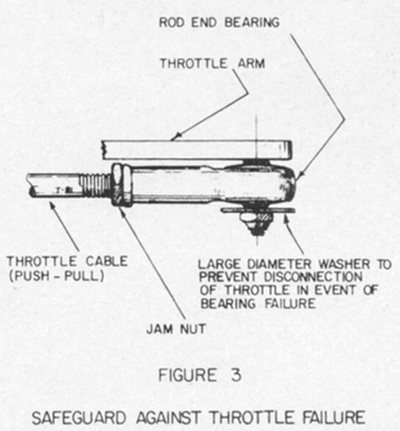
Rod end bearings have been known to literally come apart after the peening retaining the ball races somehow failed allowing the bearings to become disconnected. This sometimes happens at the throttle control linkage at the carburetor. It is a wise builder who takes the precaution of installing a large diameter washer between the nut and the bearing to prevent its total failure. To be successful in preventing this type of failure, the washer must have a diameter somewhat larger than the hole in the bearing flange (see Figure 3).
When you install a rod end of the self-aligning type bearing, you must be able to see or at least detect a slight movement in the push-pull tube or rod when you rotate it between your fingers. Check for this freedom of motion in both extreme control positions.
A self-aligning rod end will accommodate quite a bit of misalignment but be sure you do not exceed its limits. See the photos for an example of where a deliberate misalignment may be necessary in a push-pull tube installation.
The maximum angle of deflection or misalignment will be reached when the outside diameter or the rod end's head touches the side of the fitting, fork or clevis in which it is bolted.
To obtain the maximum benefit of a rod end bearing, its inner race must be securely clamped to the attaching fitting or structure otherwise the bearing action may not be activated and the rod end could, instead, rotate around the bolt.
push-pull tube actuated bell cranks (and similar push-pull tube linkages) must be limited in travel to prevent an inadvertent "locking" or jamming in an extreme position or by being rotated past center. In addition, push-pull controls should have positive stops built into the system at both ends to limit the travel range of ailerons, elevator and rudder. One of the stops may be located at the control surface.
For That Final Inspection
After you have completed your final installation and have adjusted the linkage to obtain the required travel and proper control surface alignment, check to see that each threaded rod end is screwed into or onto its mating terminal sufficiently to engage at least 3/8 to 1/2" of the threads. Rod end bearings with internal threads will have a small inspection hole through their shanks. The mating terminal ends should always be screwed in far enough that a test wire probe cannot be poked all the way through the inspection holes.


