Hoerner Wingtips Tanks for Sonerai II – Part 4
By Bill Evans, EAA Chapter 266, EAA 794228
The main reason for building the Hoerner wingtips, of course, is to provide additional fuel capacity sufficient to restore the aircraft’s range after installing a larger Jabiru 3300 engine. It burns more fuel and has more power, providing performance improvements in 17 areas. Nice!
Building the fuel compartment. Total fuel capacity increases from 16 gallons to 22. With the J-2200 engine, flight duration is 3.7 hours. The J3300 engine with 22 gallons of fuel provides a flight duration of 4.2 hours. It may not be obvious from this, but the J3300 engine carb has a fuel economizer kit which saves a little fuel. The 40-millimeter Bing carb came with that kit installed.
If you do the calculation for pounds/horsepower/hour, the J2200 engine burns 0.6 pound of fuel per horsepower per hour. I ran it that way to get a little extra cylinder cooling in the hot weather. There is no mixture control.
The J3300 engine burns 0.39 pound of fuel per horsepower per hour. In my world that is a significant saving. At 75 percent throttle, the J2200 engine delivers 56 hp for 4.2 gallons of fuel. At the same 75 percent throttle, the J3300 engine burns 5.2 gallons of fuel, delivering 106 hp.
Mileage. The same airplane gets 110 mph from the climb prop, consuming 4.2 gallons of fuel or 26.2 mpg. With the J3300 engine and a cruise/climb prop, an airspeed of 180 mph is calculated. At 5.2 gph, the mileage is 34.6 mpg for the same reason – 25 percent better mileage. Oh, the things we do for the environment!
That fuel economizer kit is a little like having your cake and eating it, too. We’ll soon find out whether it’s true.
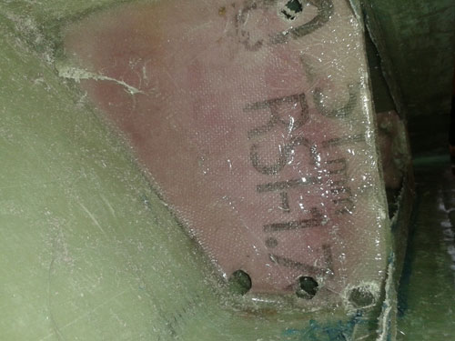
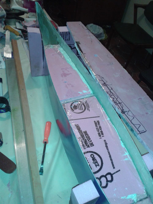
End bulkheads and fuel baffle. One of the plugs used to lay up the wingtip was saved to use for the fuel tank portion of the wingtip. We used the plywood template to hold the wingtip to a size that fits the wing profile. Once the size is set, the four end bulkheads are cut out of the polyurethane (pink foam) and glued in place using epoxy resin thickened with micro balloons such that the resin is like a paste. Once dry, two layers of 6-ounce fibreglass cloth are used to glass the end bulkheads into the wingtips on the inside only. The bulkheads are 1-inch thick.
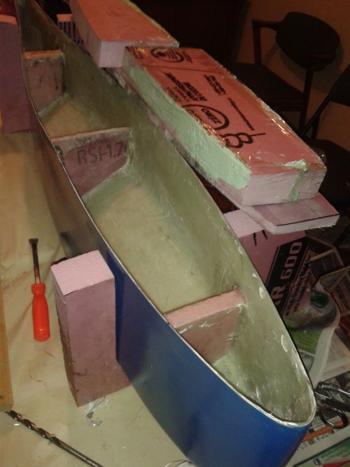
Halfway between the end bulkheads, a fuel baffle is fitted and glassed in on both sides. Three 1/2-inch holes are cut at the lower side of the tank and one 1/2-inch hole at the top to provide venting between the compartments. The edges of the holes are sealed with the epoxy putty to prevent fuel from soaking the foam.
We did not think the long inboard fuel bulkhead would be adequately supported by sealing it in from the outside only, due to the possibility of turbulence. Therefore we also laid up four fibreglass angles, using foam blocks covered in plastic wrap. These run the longitudinal length of the fuel compartment and are 1 inch on each side and about a foot long trimmed to fit the fuel compartment. Shorter angles are similarly fabricated to fit inside the fuel tank at each end. The inboard bulkhead is glassed to these angles. The angles are allowed to cure and then be removed from the foam blocks. We used clamps and epoxy resin to install those four long angles and the two end angles.
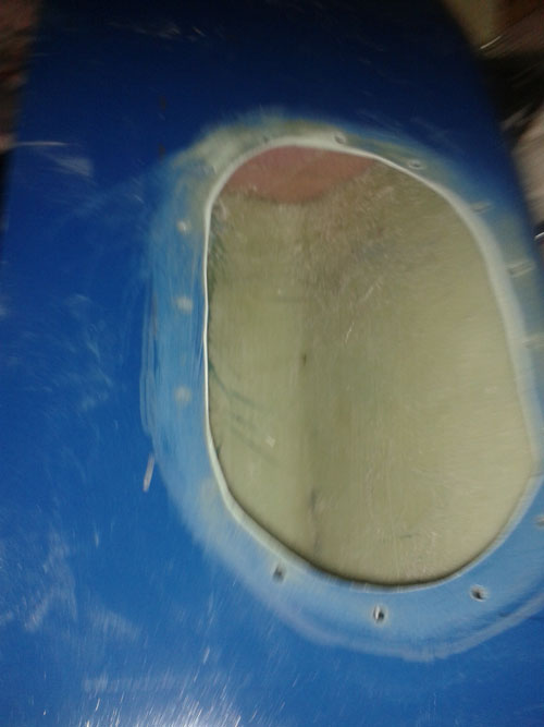
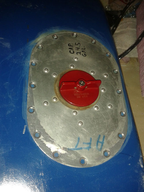
Refueling adapter (nut ring). Our refuelling adapters were purchased at surplus, reportedly from a Navajo’s tip tanks. Some pilots say they’re used on Barons. It’s just one of those mysteries…
Now, we chose the shape of the upper surface of the wingtip to provide a flat surface about a foot long so that these refuelling adapters fit. You need to do the same for whatever adapters you choose.
The first thing you need to do is cut out a flat ring of 0.032 aluminum sheet at the same profile as the adapter. We then cut ours to be 3/4 inch wide to accommodate clip nuts. We used No. 10 AN machine screws, so you also need clip nuts the same size. Screws are cheap; clip nuts are expensive. By installing these adaptors, now you can use self-locking nuts which also provide some sealing of the threads.
You could purchase the ProSeal type of fuel tank sealant from Aircraft Spruce or several other outlets (API, Aviall, etc.). It costs about $20 for a tube. You need a drill to mix it and a dispenser to apply it. So we looked around at a local auto parts store; it recently added Permatex 38401 sealant. No doubt Herndon Products has something similar. This sealant is about $7 a tube, it resists gasoline, and it can be squeezed from the tube. So…it was applied to the facing surfaces; a dab to the screw holes and the adapter was installed; and it tightened the screws right down. This sealant dries quickly, so get it done.
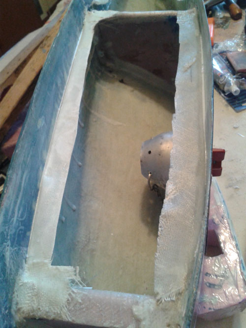
Once the fasteners were tight, we applied a bead to the exterior edge of the adapter plate and to the inside edge of the plate inside the fuel compartment. This is why we left the inboard bulkhead off until the adapter was installed.
Once the refuelling adapter is installed and sealed, the fuel tank may be closed by installing the inboard fuel bulkhead. Verify again that the profile of the wingtip fits the plywood template before glassing in the bulkhead. You are doing this again because six angles have been glassed in and clamped. The wingtip profile may have changed.
We did this bulkhead installation in three steps. First, the fuel side of the foam bulkhead received two layers of 6-ounce cloth and resin. Over that, we applied the thickened epoxy resin to form a type of gel coat to better resist the fuel. Also, use this mix to gel-coat the inside of the end bulkheads for the same reason. We used this process before when laying up the wingtip itself.
Epoxy resin has been shown to resist both 100LL and auto gas fuels. Nevertheless, pinholes may exist in the layup. The gel coat is intended to seal the layup perfectly. We certainly don’t want fuel leaks.
Once that resin is cured, mix up about 4 ounces of the thickened resin to paste consistency and glue the cloth side of the bulkhead to the angles and bulkheads. I put the epoxy paste on 1/8 inch thick and used some weights to press the bulkhead in place. We decided to let the resin paste cure before glassing the bulkhead in.
With the bulkhead glued in place, we cut out the two layers of the 6-ounce cloth such that they seal in both end bulkheads and the inboard bulkhead with an inch of cloth overlapping onto the wingtip all around the fuel compartment. If strips of wood are clamped in place to hold the edges of the cloth, use plastic wrap to cover the strips and clamps.
Due to Sun 'N Fun the next article will appear in the June issue where we will discuss installation, hookup, the fuel fittings and hoses will be installed, and weather permitting, the Hoerner tips installed. Since spring is officially here, the new aileron mass balance weight installations to the wingtips may have to wait.
