An Adventure in Dynamic Propeller Balancing
By J. Davis, EAA 588164
June 2015 - At my recent visit to Sun ’n Fun International Fly-In & Expo in Lakeland, Florida, I looked closely at an idea I’ve been thinking about for a couple of years: DIY dynamic prop balancing. There are a couple of companies who provide basic, entry-level systems at a reasonable cost, and my thinking was that I had the ideal situation to offer the service to the homebuilt/experimental community. Interested parties could fly into my strip, taxi up to my shop, and get their props balanced. And ideally, I could recoup my investment in a fairly short amount of time.
So I ran my idea past our local tech rep to see if he thought that there would be enough demand to justify the capital outlay. He informed me of a fact of which I was not aware: Purple Hill Aviation, located at CYQS, offers just such a service. So I abandoned the investment idea, and having wanted to get my own prop balanced for quite some time, I set up an appointment.
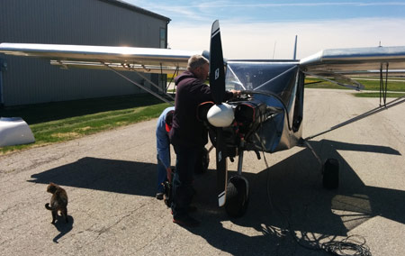
Mounting the accelerometer while Scotty the shop cat looks on
A lot has been written regarding the benefits of dynamic propeller balancing. Apart for the obvious desire to reduce vibration felt in the cockpit, my main goal was to verify that vibration harmful to the engine – particularly the crankshaft and flywheel of my Jabiru 3300 – was reduced to a minimum.
The principle of dynamic balancing is fairly simple: Two transducers are mounted on the engine.
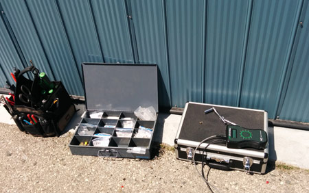
One is a vibration sensor (accelerometer) mounted as close to the transverse centre line of the engine as possible.
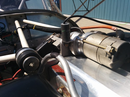
Close-up of the vibration sensor
The other is an optical sensor which sends an infrared signal to a piece of reflective material stuck to a prop blade.
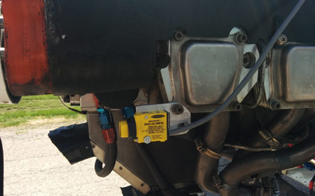
Close-up of the optical sensor
The engine is then revved to the desired rpm, usually the normal cruise rpm. In my case, this required attaching my airframe to a stationary object (a truck) since my little Matco disc brakes are not capable of holding the plane at 2,860 rpm.
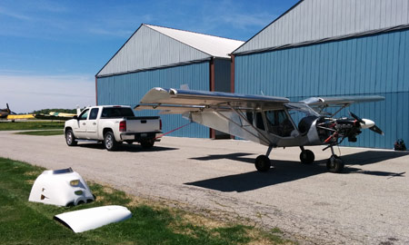
Making sure it stays put!
Given the data input from these two devices, the software then computes the amount of vibration, measured in inches per second (ips), and the location of that vibration, measured as an angular offset from 0 degree (the reflective tape on the prop). Based on this initial reading, the operator places one or more penny washers behind one of the spinner screws, and the process is repeated.
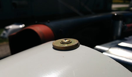
The first weight attached to a spinner bolt
Each readout gives the operator more information, and eventually the reading approaches 0.07 ips, the goal. Typically, the weight will not be conveniently needed at the exact angular location of a spinner screw, in which case the weight is split between two screws.
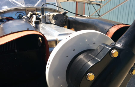
The spinner bulkhead drilled for final hardware
Once the angles and weights are determined, AN3 bolts and washers are installed on the spinner backing plate, or bulkhead.
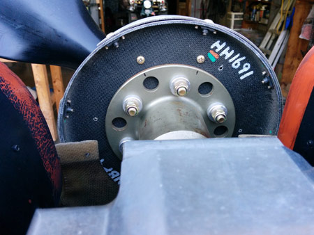
Attaching the final hardware
A couple more run-ups for fine-tuning are required, and the job is finished. Sensors are removed, cowls are replaced, and a logbook entry is made.
In my particular case, the initial reading was 0.23 ips, and the final reading was 0.07. Because 0.23 is not particularly bad, there was no dramatic improvement noticeable on my flight home. But I feel that it was a worthwhile expenditure in that now I know for certain that any potentially damaging vibration has been reduced to an absolute minimum.