My POV of a DIY AOA-LRI Indicator (FWIW, YMMV, LOL)
By J. Davis, EAA 588164
July 2015 - Since the angle of attack (AOA) is defined as the angle between the relative wind and the chord of the airfoil, a true AOA indicator must usually have a rotating vane that will measure this angle. About 15 years ago, my very first device was a simple vane clamped to the pilot-side wing strut, in the airstream. It was commercially available under the name of the Bacon Saver and, once calibrated, did the job. As far as I can tell, these simple devices are no longer available, but a DIY facsimile would be easy.
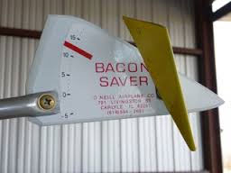
My first AOA, the Bacon Saver.
I had a math professor years ago who liked to illustrate a concept with a story: “Imagine a seventh grade schoolroom with all the boys lined up on one side, and all the girls on the other. As the second hand on the wall clock reached straight up, the boys would approach the girls by exactly one half of the distance between them. With each subsequent minute, the boys would once again halve the distance to the girls. Technically, the two groups would never meet, because the other half of the distance would always remain. But eventually, the boys and girls would be close enough for all practical purposes!” [1]
That's the way I like to think of the stall-warning device I’m currently using. It’s not a true angle of attack (AOA) indicator, but for my money, it’s close enough for all practical purposes.
Usually described as a lift reserve indicator (LRI), this device measures the differential pressure coefficient between two pitot-type tubes located at a fixed angle to each other. My installation currently uses an analog gauge to display this difference, and the angle of the sensor assembly is adjusted to calibrate the pointer on the gauge to some (arbitrary) position during repeated full-stall landings.
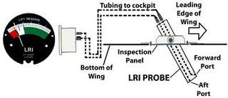
A basic schematic.
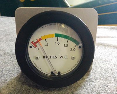
A typical analog gauge.
There is room for creativity in the fabrication of the probe. You just need to end up with two pitot tubes fixed at some arbitrary angle to each other (usually 45 degrees). There are plans on the Internet that suggest drilling a 6-inch-long by 1/2-inch aluminum bar.
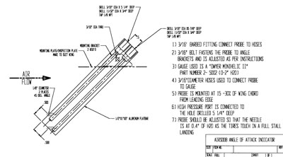
Open-source plans.
Thinking that deep-drilling that aluminum would be onerous, I opted to connect two blocks of nylon that I had hanging around with aluminum tubing.
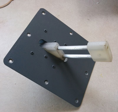
My LRI sensor.
Angled holes are drilled through the nylon into the tubes from each face of the lower block. A transverse hole through the top block allows overall adjustment of the probe assembly angle for calibration purposes.
Although I have prototyped a digital indicator for this probe - one that uses a solid-state differential pressure chip and LEDs in a red-yellow-green configuration - for now I elect to use a simple analogue gauge.
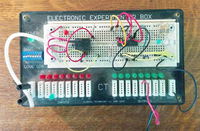
Breadboarded digital LED indicator.
The gauge is made by Dwyer and is the 0-2-inch H2O model as called out in the plan above. I experimented with using my own colour-printed faceplate applique, but I eventually settled on using the Dwyer-supplied faceplate and simply applying standard airspeed indicator red/yellow/green arc tape instead. I inset the gauge into my glare screen, so it would easily be in my field of vision during normal operations, especially takeoff and landing. Connection is as simple as running two nylon lines between the AOA probe and the gauge. No electrical connections are needed unless you want to illuminate for night flight.
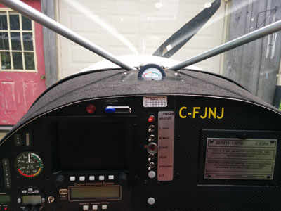
Dwyer gauge set into my glare shield.
Calibration is accomplished by noting the needle position during full-stall landings at the moment of touchdown. Back on the ground the probe’s angle is then adjusted so that the needle will be at the red/yellow border at the point of stall. This may take a couple of test flights to get it right, but once it’s done, you’re done.
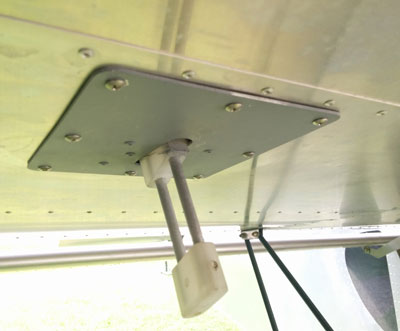
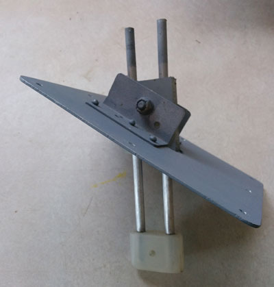
Mounted under wing.
Flying with an LRI can optimize takeoff and landing distances. On takeoff, the aircraft is ready to fly as the needle moves from the red into the yellow zone. The final approach on landing is flown with the needle centred in the yellow zone. The base to final turn should be made with the needle in the green.
This system, while not a true AOA indicator, is nonetheless a valuable aid to safe and efficient flight.
Blue skies, safe flight!
[1] - Zeno’s Achilles paradox.
