Aircraft Wiring... Where Do You Begin?
By Tony Bingelis (originally published in EAA Experimenter, March 1995)
If you have never done any wiring, most likely you will not have any of the tools or wiring supplies you will need to fabricate and install your aircraft’s electrical system.
If that is the case, then the first order of business would be to do a bit of shopping or scrounging for the essentials you will need to get the job under way.
Tools Needed
Fortunately, the tool requirements are minimal as are the skills needed to use them.
Just about the only special tools you will need are a pair of wire crimping pliers and possibly a good wire stripper. Other tools, like needle nose pliers, screwdrivers, a pair of diagonals, wire cutter, an electric drill with an assortment of small bits, and a few small wrenches which you probably already have, are a few of the necessary items.
Other Needs
As for materials and parts needed, much will depend on the complexity of the aircraft to be wired. You will need a small roll of adhesive tape and a fine point permanent ink pen for labeling your wires. Of course, even the simplest system requires the installation of electrical wires, connectors, fuses or circuit breakers, and the accessories you want to operate.
Since the aircraft’s electrical system is determined by its wiring, let’s start there.
Electrical Wire
The wire permitted for use in military aircraft, and blessed by the FAA, is identified by the specification, MIL-W-22759/16. There are a lot of different types of wire out there where you are, and a lot of it will find its way into homebuilts . . . maybe even into your own.
Electrical wire can be found in the Radio Shack stores, auto parts stores, electronic outlets, fly markets, and homebuilder catalog outlets. I dare say much of it does not measure up to the military standard mentioned - primarily, I suppose, because the insulating coatings would, in the event of fire, give off toxic fumes. The smoke and fumes could well incapacitate the crew (that’s you, amigo). The most important consideration in wire selection is that the wire be made up of twisted wire strands... not a single solid wire core. Stranded wire stands up better under vibration and is less likely to break.
A wire, in order to be useful, must be connected to something somehow . . . the crimping tool makes this possible.
That All Important Crimping Tool
A wire, in order to be effective, must be secured to a reliable connector at each end. In aircraft, electrical connections are made using insulated crimped terminals.
Although soldered connectors are also used, they are utilized primarily for making avionics installations.
In that our subject is intended to help you get started on your electrical system, our discussion will focus on the crimp type electrical connections only.
You can get off to a good start by obtaining a good quality (made in the USA) crimping tool for your wiring job. My favorite is the 3M TH-450 multi-purpose crimper.
Like many other brands on the market (mostly from the Far East), this crimping tool also has a built-in wire stripping capability for a number of wire sizes.
There are several sources for crimping tools, among them are the Radio Shack stores, auto parts stores, Sears, and most hardware stores. Quite often the crimping tool is sold as part of a wiring kit packaged in an impressive plastic display case. Included in such a kit would be an assortment of insulated type terminals. Because of the assortment of terminal sizes included, you might consider this to be an acceptable starter set.
As soon as you acquire your crimping pliers, try making a few test crimps. For example, a well crimped insulated ring terminal should resist a fairly strong tug (about 5 pounds) without allowing the wire to separate from the insulated connector.
Some of the cheaper varieties might not crimp the wire effectively, and that is not good. An unreliable electrical connection, or one that becomes completely separated, is something you don’t need to have happen in flight.
Making A Crimped Connection
Be sure the insulated ring terminal you select is the correct size for the wire to be connected. Only the insulated portion of the terminal is color-coded to identify the wire size it will accept. For example:
1. A red insulator identifies that the terminal is intended for use with wire sizes ranging from 18 to 22 AWG.
2. A blue insulator is for use with somewhat larger wire sizes, 12 to 16 AWG.
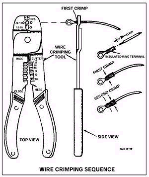
3. A yellow insulator identifies the largest of the insulated type terminals, intended for use with wire sizes of 8 to 10 AWG. Your crimping tool can accommodate all three sizes of the insulated terminals.
On most crimping tools each of the crimping dies, notched in the jaws of the crimping tool, is color-coded to identify the insulated terminal it will accept.
To connect an insulated type ring terminal to a wire, proceed as follows:
1. Select the correct insulated terminal for the size of the wire to be connected. For example, if the wire size is 18 AWG, use a terminal that has a red insulator.
2. Using the wire crimper’s built-in wire stripper, insert approximately ¼" of the wire in the crimping tools’ stripping notch. Squeeze the crimping tool handles together and rotate the tool about 45 degrees each way to impose a cutting action on the wire’s insulation. Pull on the wire and a ¼" length of insulation will be stripped nicely from the end of the wire.
You could use a separate automatic wire stripper tool which may or may not do a quicker job. For that matter, even a knife will do in a pinch if you are careful not to cut into the stranded wires.
You may find it hard to believe that you only need to strip away approximately 3/16" to ¼" of the insulation from the end of the wire but it is true.
3. Next, twist the bared wire strands a bit with your fingers. This will tighten the protruding wire strands and help ensure getting a better crimp on the wire when you install the terminal.
4. Insert the bared wire in the ring terminal so the insulated edge of the wire bottoms against the back end of the metal portion inside insulator (terminal). The bared stranded wire should barely protrude from the other end (ring side) of the terminals metal grip.
5. With the wire firmly bottomed inside the insulated terminal, slip the crimping pliers over it. Make your first crimp over what you think is the middle of the metal wire grip inside the insulator. This should be approximately the first 1/3 of the length of the terminal’s insulator. Apply a good squeeze . . . not so hard, however, that the insulation is cut by the crimping tool. On the other hand, the crimp should be sufficient to lock the wire inside the terminal.
6. Check your success by gripping the terminal with the fingers of one hand while you tug on the installed wire with your other hand. If the connection won’t separate with a tug of approximately 5 pounds you have a winner. If it comes apart:
a. You didn’t crimp it hard enough, or
b. Your wire size is too small for the insulated ring terminal you used, or
c. You may have made the crimp too far back and missed crimping the metal portion of the terminal inside the insulator.
7. If your connection passes its "tug test," make a second crimp near the back end of the insulator to squeeze it snugly around the wire’s insulation. The purpose of this crimp is to firmly support the wire and help absorb some of the stress to which the connection might be subjected to from in-service vibrations.
Tips For Simplifying Your Wiring
Whenever possible, pre-wire (attach all the wires) to each circuit breaker and fuse assembly, the master switch, and especially the ignition switch BEFORE installing it.
Believe me, this is much easier to do when you have the unit laying on the bench where you can see what you are doing. Obviously, if you install the switches, circuit breakers, fuses or lights in the instrument panel first - and then try to make the connections from behind, you will have a difficult time doing so. You might as well be prepared for the ordeal by getting a few extra screws and lock washers together because you will probably be dropping a few before you get everything connected.
NOTE: It is said by those who know that whenever you drop a washer, screw, or nut in your airplane it will vanish before your eyes and will not be found again until you no longer need it. Other than that profound observation, the main drawback to the technique of pre-wiring switches and circuit breakers is that you will have to allow generous lengths for the wires because you may not be exactly sure how long each wire has to be.
However, to compensate for this shortcoming, the pre-wiring technique will enable you to better organize your wiring without creating an excessive crisscrossing maze of wires.
In the interest of making your future maintenance efforts less painful, try to locate your power bus and ground terminals where they will be easily accessible. Install these units so you will have space for manipulating a screwdriver or wrench when attaching the many wire terminals to them.
Think about it. Is it better to orient the terminal blocks so the screw heads are up? Down? On the side? Which provides the easiest access for installing the connecting screws?
One problem builders create for themselves is making future access difficult in other ways. For example, crowding the installation of fuses, circuit breakers, connectors and instruments . . . even when you have plenty of panel space.
I think circuit breakers (fuses) and switches should be spaced no closer than one inch apart when possible.
Circuit Identification
Label or number each wire as you connect it. Later you might be hard pressed to identify the wire and its function. Label the wire approximately 6" from the unit to which it is attached. You can make small tag labels using adhesive tape and a Sharpie pen. At any rate, the marking should be in waterproof ink. Using masking tape tags is not recommended except for temporary use. The masking tape tags age rapidly and become brittle. In addition, the markings tend to rub off or fade.
Wires can also be identified using a special wire marker tape which has a pre-printed number on it. The tapes have numbers running from 0 through 9.
Simply cut off a bit of tape with the number you want and wrap it around the wire to identify it. It is a simple and neat way to do it. Of course, the drawback is that you have prepared a "poop sheet" to remind you what circuit a particular number is assigned to. Similarly, some builders identify their fuses and circuit breakers by numbering them. This is a lot easier than trying to find descriptive labels small enough to attach above each fuse or circuit breaker installed in your instrument panel.
Don’t be in too big a rush to install tie wraps to organize the wiring. Only too often you will have to cut many of them away as additional wires are introduced. Temporarily, you can use some of those common wire twists or string to clamp two or more wires together.
Shopping List
• Wire crimping tool
• Adhesive tape, small roll
• Sharpie pen - fine point, black ink
• Wire: #18 wire gauge for most of the electrical system, #16 wire gauge for landing and navigation lights, #18 wire gauge shielded wire for connecting the magnetos, #8 or #10 wire for connecting the alternator, #4 welding cable for connecting the battery. Use #1 or #2 if the battery is way back in the fuselage, or if you generally have severe cold winters.
• Sufficient numbers of insulated ring tongue terminals for connecting the above listed circuit wires. You will probably need twice as many ring terminal connectors as you think you’ll need . . . especially the red ones. Buy a package of a hundred for less than $10 at an electronics store as opposed to buying a small package of 5 in an auto parts store for about $1. Good buys for insulated ring terminals may also be found at most fly-in flea markets.
• A circuit breaker, or a fuse/ holder, for each important circuit. *A switch or a circuit breaker switch for each circuit you must control: flaps, nav lights, strobes, fuel pump, avionics master, master switch and ignition switch, for example.
Switches must be rated for the current they will have to carry. Beware of the commonly available toggle switches.
Although such a switch might be labeled at 15 amps (125V.AC), in reality it is only capable of handling but a fraction of that in a 12 volt DC circuit.
Auto parts stores, on the other hand, have switches rated for 12 volt DC operation and can handle the labeled current in any 12 volt system.
