Spring Steel Landing Gears
By Tony Bingelis (originally published in EAA Sport Aviation, May 1979)
LANDING GEAR INSTALLATIONS are built-up of parts and subassemblies. The fewer the parts, the better the gear . . . in theory at least. Not only that, but wouldn't it be easier to build? It's no wonder that the average builder believes a spring steel gear to be the ultimate in landing gear simplicity. After all, what could be easier to make than a single-piece landing gear leg? No need to cut, and bend fittings and parts to make a component, which must then be jigged and welded to some other part or component. No sir! The gear's appearance speaks for itself . . . or does it?
Don't be misled by appearance. The means of attaching a spring landing gear to the structure is concealed from view, and it is this essential internal provision that complicates the gear's installation, and inevitably results in additional weight. The internal brackets and trusses used to support the spring gear legs are generally as difficult to fabricate in aluminum and wood structures as they are to fit and weld in tubular structures. Consequently, the total weight of an installed steel spring gear, regardless of the type of structure, may be greater than that for other gear types.
Weigh a typical set of spring steel gear legs and you will find they tip the scale at 37 to 40 pounds. Add 12 or 15 pounds per wheel, tire, tube and brake, plus another 4 to 8 pounds for the internal attachment cradle and reinforcements, and you will learn that the gear installation tops 75 pounds.
However, in exchange, there are the benefits of a maintenance-free, low drag, installation. And, a low drag installation it is, even without the benefit of fairings. I would venture to say that it is second only to a retractable gear for aerodynamic efficiency. So, in spite of its weight handicap, the flat spring steel landing gear is a good functional one for most purposes. Admittedly, a few builders don't like its wing-wobbly behavior on the ground, but I can assure you, it is a very minor problem.
Notes On Modifying Cessna 150 Spring Steel Gear Legs
Designing a spring steel gear is an engineering adventure involving mathematical analysis of gear leg deflection vs. energy absorption, descent velocities, and at least a stress analysis of the gear attachment structure. All this is far beyond the aspirations of even an avid builder. Most prudent builders will first try modifying a pair of second-hand Cessna 150 spring steel landing gear legs. And thanks to some happy coincidence, a few of them may be able to install the gear legs without any modification. However, should you or I hope to do the same, we would undoubtedly find that we will have to do it the hard way. That is, cut them down, both in length and in width. Not only that, but we would probably have to rebend the ends to fit. Such extensive modifications are probably the rule rather than the exception, because, unless your airplane is approximately the same size and weight of the donor Cessna, the gear will be too heavy and too rigid for the lighter, smaller homebuilts. Remember, it was originally designed for a large-span airplane weighing approximately 900 pounds empty and up to 1500 pounds loaded.
On a much lighter airplane, it will be too stiff. In addition, if you also find it necessary to shorten the gear legs to fit your homebuilt, the stiffness effect will be compounded and you will have to cut down the width of the gear legs to compensate for the lighter weight.
Most salvaged gear legs you may obtain will undoubtedly have been made of a modified 6150 Chrome Vanadium steel, and heat treated to a Rockwell C value hardness of up to 48, giving them a tensile strength of approximately 237,000 psi.
Those heavy 5/8" thick hunks of steel can look like a hopeless cause laying there on your work bench. However, I found that Cessna 150 spring steel gear legs, for example, in their normal tempered state may be cut down on a metal-cutting band saw. Use a new blade and take your time. The edges of the cut will be smooth and without the locked-in stresses that develop when a cutting torch is used.
The edges of the gear legs should be radiused as is customary, not only to reduce stress but also to aid in the appearance and streamlining of the gear. Always smooth-finish the edges of the gear legs before starting any bending operations.
I guess more gear legs have been ruined by builders trying to cut the stock gear down in width and length with a cutting torch than by any other single thing they may do to the legs.
You may as well face it, rebending and heat treating a spring steel gear leg in your own work shop, with a single welding torch, is not practical. You simply cannot get enough uniform heat on it, over a wide enough area, to allow you to bend the metal without inducing stress cracks. Countless builders have tried to anneal and straighten, or rebend, the gear legs themselves but only a few have succeeded while many have thoroughly botched the job.
You would probably have better luck taking the gear legs to an automotive spring shop. These shops have the necessary furnace for heating and annealing springs and the fixtures and devices for bending and forming them. Some of them also have the capability for making coiled springs but the degree of reliability and competence of these shops varies greatly. One will have the skilled people and the machinery to do just about any kind of spring work while another would do well to put a stress-free bend in a paper clip. About all I ever had done at one of these places was to have the gear legs annealed and rebent to specific template angles (which you should provide). It is possible they could also put in additional arch (camber) in a gear leg that is otherwise O.K. Bends normally should be made parallel to each other to obtain proper wheel alignment between the two legs. Since bends must be made with the legs in a red-hot, soft condition, it would be wise to diplomatically encourage the spring man to be extra careful for your airplane's sake, and avoid making clamp marks across any of the bends.
After the modified gear has been bent to shape and then checked in position for alignment, it will have to be taken to a heat treatment facility. If you think your spring shop is able to heat treat your gear to your satisfaction, fine. If not, it could mean a trip to the big city for you.
At the heat treatment facility, the gear legs will first be heat treated for stress relief and then cycled through the proper process which results in finally tempering them to a specific hardness. A Rockwell C value of at least 40 but no more than 48 should put your gear within the proper range of hardness. The higher the Rockwell number, the, greater the tensile strength of the metal. Heat treating to too low a Rockwell number may result in gear that is too soft. It could develop the `sags' while in use. Too high a Rockwell C value can result in a tough but brittle gear.
Following the heat treatment, the gear legs should be magnafluxed to determine if they came through the process without cracks and suspicious stress areas.
Finally, if the facilities are so equipped it would be worth having the legs shot-peened for increased fatigue life and to inhibit any tendency for cracks to start.
With all the work involved in modifying a Cessna 150 gear, it might be that you would find it easier and more economical to start with steel stock instead . . . especially if you would have to pay very much for a pair of old landing gear legs. On the other hand 6150 spring steel is not priced cheaply these days, either. So, weigh the pros and cons and proceed accordingly.
About Building Your Own
Building a spring steel landing gear from plans with the gear specifications on them is one thing. Building one by relying on your instinct is quite another. Still, sometimes it must be done, particularly if you have no source for buying a ready-made gear and the old reliable Cessna 150 legs simply cannot be adapted to your requirements. The first major problem you would encounter is that of deciding what material and what dimensions to. use. If you can't get engineering assistance for the custom-design of your gear, the least you can do is to base your gear design on other representative installations that have proved to be successful. For example . . . here is how I would determine how thick the gear legs should be. I already know that the Cessna 150 gear is 5/8" thick. I am also familiar with several successful homebuilts utilizing 1/2" thick gear legs. Therefore, I can safely conclude that steel spring gear legs for aircraft with gross weights ranging from 1400 to 1500 pounds could reasonably be expected to require steel stock 1/2" to 5/8" in thickness with the width approximately that of the Cessna gear. Of course, the length of a gear leg also has an effect on its flexibility although a change in thickness produces a relatively greater effect on stiffness.
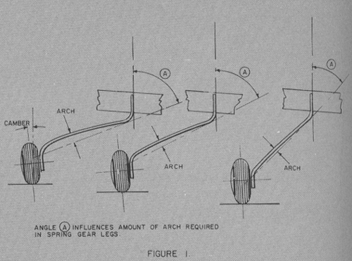
A spring gear that is too flexible could, sooner or later, lead to propeller damage during one of those rare, other-than-good, landings. A too-flexible gear might also increase the airplane's propensity for ground looping. There is another factor affecting the gear's flexibility and that is the angle at which it projects from the wing or fuselage, that is, the angle formed between the gear leg and the vertical axis of the aircraft. This angle has a bearing on the gear leg's dimensional design too. The more horizontally the gear leg projects from its point of attachment, the more arch or curvature that must be induced in the gear leg. See Figure 1.
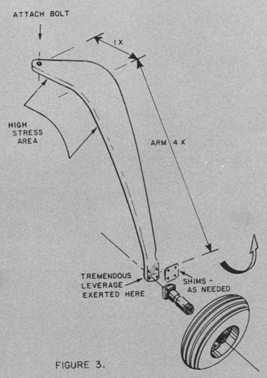
The second big problem is one of installation. How do you mount the gear in the structure? Because the gear's effectiveness is dependent upon its spring action, it is very important to avoid the introduction of stress areas by drilling holes in the gear legs. Usually, the only holes permitted are the single bolt hole used for attaching the gear and the four others at the lower end for attaching the axle. No holes should even be drilled in the areas of high stress. See Figure 3.
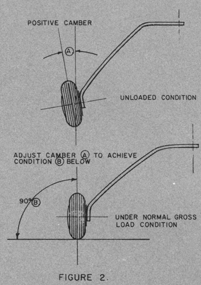
This limitation means that, in addition to that single attachment bolt, some sort of cradle and clamp must be built into the aircraft's structure which will clamp and hold the gear leg in position without adversely affecting its flexing. The point of attachment in most aircraft structures is so limited that it results in a very short mounting arm which must absorb all of the landing shocks and loads imposed by the long gear leg. The principle of the lever is most obvious here and quite adverse in that the long gear leg, acting through the wheel, serves as a lever, and in so doing, imposes considerable strain on the landing gear attachment. The highly concentrated loads imposed on the mounting makes it a difficult gear to install in wood and composite aircraft as some means for diffusing these loads is necessary. It is sometimes easier to make the gear legs first and then fit them to the structure with whatever trusses and cradles are needed. Otherwise, the gear might be difficult to align. But, even in alignment, the spring gear is really the easiest gear to install because a slight misalignment can easily be corrected by using steel tapered shims between the axle and the gear leg. These shims make it possible to vary the camber as well as to adjust for any undesirable toe-in. See Figure 3.


