Hoerner Wingtips Tanks for Sonerai II - Part 6
By Bill Evans, EAA Chapter 266, EAA 794228
July 2015 - We begin this part with the wing outboard rib. The challenge is that the original wingtip was riveted between the rib and spars inside and the wing skin outside. How would we make a wingtip so close to tolerances that it would fit into this 0.032 space?
We didn’t. Rather we planned from the outset to fit the wingtip over 2024 by 0.032-inch strips and use clip nuts to screw each wingtip in place. The strips have some flexibility as does the wingtip. Further, clamps can be used to help us get things to fit. By clamps, we mean the 12-inch machinists clamps made earlier.
The technique is first to insert the 0.032-inch strips (about 1.5 inches wide) between the outboard rib and the wing skin. Then the wingtip is placed in position and pressed inboard until it is flush with the edge of the skin. In our case a bit of trimming and sanding was required to get the wingtips perfectly flush.
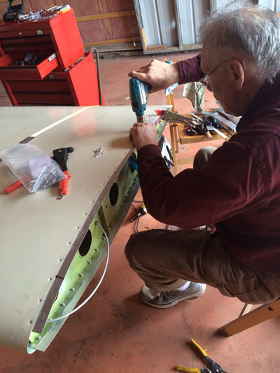
Match-drilling the strips
Once the strips are placed in the correct positions, they should be clamped in place while the original rivet holes are used to pick up the holes in the strips.
Rivets holding strips in place
In our case the original rivets were 1/8-inch; however, drilling them out meant that not a few holes went slightly oversize. We were unable to obtain 9/64-inch rivets, but 5/32-inch rivets are carried by Tec-n-Tec fasteners in Montreal. Further, they have rivets with SS shanks, and they work well. Our application needed more than a bag of 100, but Tec-n-Tec sold us a bag of 110. There were a few to spare. They are also much cheaper than anywhere else.
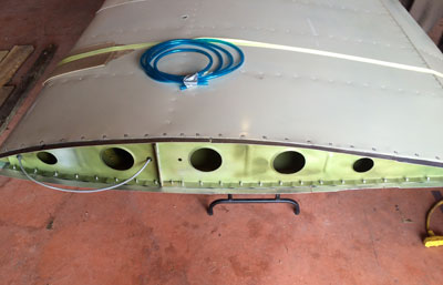
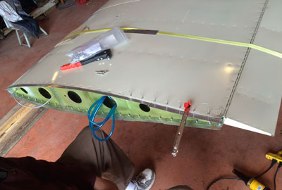
Attachment strips fitted
The photo above shows what the strips look like when drawn tight. Several clamps were used, with rivets for alignment since we do not have 5/32 Clecos. It may not be possible to draw all the rivets at the same session. Either you are young and your hands are not yet at your full strength or not so young and the usual aging arthritis kicks in. You only get one pair of hands so don’t force them.
Now’s the time to drill the new wingtip and aluminum strips for the clip nuts and flush screws to be used to retain the Hoerner wingtips on the wings. In this case we needed more clip nuts and No. 8 screws than our spare parts boxes provided. We could have bought them at Sun ’n Fun at Lakeland or waited for the sales at Oshkosh. But there was no need since there is a Fastenal store nearby, and for the last few years they have been selling screws and other fasteners to the public, albeit by the box or bag. As with the rivets, we needed about 100 of each. One hundred is enough because we won’t want to screw the wingtips to the ailerons. Gasp!
Trailing edge
It suited our application to retain the original wingtips until the Hoerner tips were installed. In this situation the originals were used to locate the holes in the Hoerner wingtips, something less than 100 of them. Once drilled to just slightly larger than No. 8, which could be 9/64, the Hoerner wingtips can be positioned and the attachment holes drilled in the strips for the clip nuts.
At this point the wingtip may be removed to countersink the holes to fit the No. 8 countersunk machine screws we bought. We also found it useful to open the holes in the clip nuts. In our case we opened them up to 3/16 inch, though for some clip nuts, 1/4 inch might be better. Some MS clip nuts contain a ridge, which fits into 1/4-inch holes. Ours did not.
You would think that all you need to do now is position the clip nuts, install the wingtips with 100 screws, and the job would be done.
Not so fast. The wingtip contains a strobe light that needs to be connected.
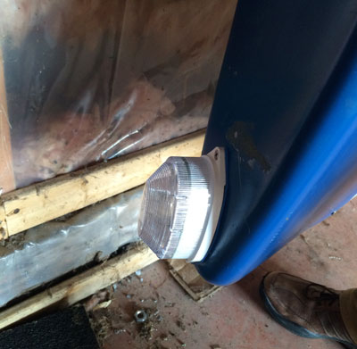
Strobe
In our case the wing wires were red and back, which made connections to the strobe wires (+12V = red and GND = BLK) easy. We used reversed male/female connections to make incorrect connections impossible.
The fuel lines need to be run, too. The fuel supply fittings are located opposite from a lightening hole in the outboard rib.
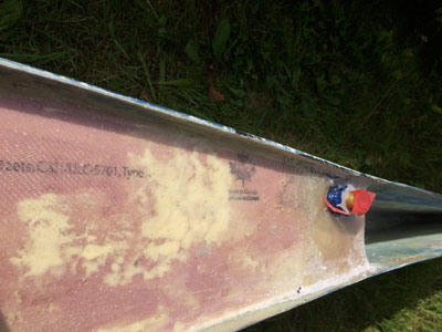
Fuel fitting
Russell fittings and fuel hose and screens from Aircraft Spruce were used to connect the tip tanks to the Facet transfer pump, which will transfer the 6 gallons of fuel into the auxiliary tank in about 10 minutes. If desired, you could transfer fuel while also feeding fuel from the auxiliary tank. I would not, due to the possibility of air in the lines, but you could. I would feed the engine from the main tank while the transfer was underway.
We used a thin wood strip to drag the fuel hose through the lightening holes. Tie wraps and fiberglass strips are used to space the fuel hose away from metal edges. Double-sided tape sticks the fiberglass strips to the ribs. Two should be enough. How? That’s what the wing access panels are for.
There are small (3/8-inch) fuel injection clamps—better suited to the application than the worm screw clamps, which are more prone to damaging the hose. You can also lock-wire the fuel injection clamps closed as a safety device.
It is necessary to use some sort of table or support for the Hoerner wingtips while the strobes and fuel lines are connected. Once done it’s wise to leak check the fuel lines and test the operation of the strobes.
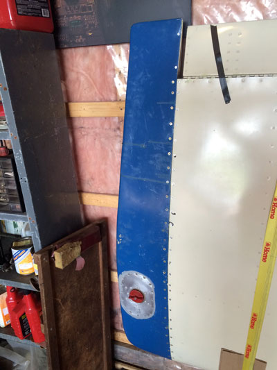
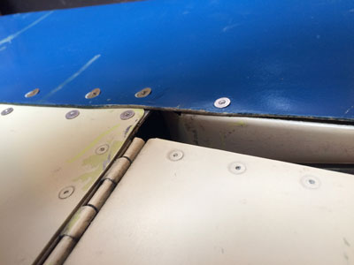
Wingtip installed
Now that the strobes and fuel lines are connected, the new wingtip may be positioned over the strips and clip nuts such that it meets the wing skins. We found it helpful to use several ice picks and some green masking tape to hold the wingtips in place while the screws are started. It seems to us to be a better technique to start all the screws before tightening them down.
From the last photo you can see the screws stop where the ailerons start. We don’t have seals yet, but the gap between the aileron and wingtip will be sealed with strip brushes.
If it ever came to that, the screws could be removed and the wingtips removed for whatever work the future required.
The editor reminds me that these have not flown and surely a final part is desired to report on the performance and the functioning of the fuel tanks. Enquiring minds will want to know just what the fuel duration now is.
We believe that our original estimate of $500 is about right. It may have gone over by 10 percent but not more. However, building the first of anything is a learning experience. While we did not have to scrap things and start over, some tasks took longer than expected. We don’t have a time log for this project, but it’s in the hundreds of hours. Nevertheless, the wingtips are completed, connected, and installed. It’s satisfying to have it done.
Expect a follow-up article on the test-flight results when that day arrives.
