A Gyro Instrument System? (Your Options)
By Tony Bingelis (originally published in EAA Sport Aviation, June 1984)
PUTTING GYRO INSTRUMENTS in a fun airplane (Volksplane, Acro Sport or whatever) makes just about as much sense as installing cruise control in a dune buggy. Besides being totally unnecessary for every day sport flying, I can think of two other good reasons for not having any gyro instruments – cost and weight. (Extra work? – doesn’t count.)
The added weight may not be too great a penalty except for small low powered aircraft. For them, a complete gyro installation becomes nothing more than a ludicrous embellishment. I estimate that a basic vacuum system with three gyro instruments will weight about 10 to 12 pounds and will cost at least $100 per pound to boot. That is a lot of extra weight and extra bucks to have deadheading most of your flights. Well, so much for gyro instruments in fun airplanes. But what if your airplane is used primarily for transportation and for fairly long flights where the weather could change two or three times before you reach your destination? No argument here. Doing without gyro instruments for that kind of flying is like doing without water on a trek through the desert. Even the installation of the lowly Turn/Bank Indicator alone could well save your hide someday. . . or at least keep you from spiraling in without so much as a needle and ball to keep your airspeed company. Of course, with the addition of a Directional Gyro and Artificial Horizon to supplement a Turn/Bank Indicator, you'd have everything possible working for you cross country or IFR flying. Those three instruments constitute what is often termed a `full panel'.
Current practice is to install a vacuum driven Directional Gyro, Artificial Horizon and an electric Turn/Bank Indicator or a Turn Coordinator. Then, in the event of a vacuum system failure, you would still have the old Needle Ball and Airspeed survival capability. However, there is no law saying that all three instruments can't be vacuum-type gyros if you prefer. If you do settle on vacuum driven gyros your vacuum source will have to be either a Vacuum Pump or a Venture. Take a peek at figures 1 through 5 to see how and where the following vacuum system essentials are installed in the systems illustrated.
Gyro Instrument System Components
1. A Directional Gyro
2. An Artificial Horizon
3. A Turn/Bank Indicator (use of an electric T/B or Turn Coordinator is highly recommended instead of a vacuum instrument.)
4. A Central Air Filter with a .3 micron filtering capability.
5. A Vacuum Regulator (sometimes called a suction relief valve).
6. A Vacuum Gage
a. A single port type or preferably
b. A two port type (differential measuring)
7. A Vacuum Source
8. A Venturi Tube (2", 4" or a Super Venture) or
b. A Vacuum Pump (either a "Wet" Pump or a "Dry" Pump)
9. Fittings
a. Airborne Free-Flow type or
b. Standard AN (Hose or Flared types) or
c. Nylo-Seal type
10. Hoses, clear plastic or rubberized (thick wall type)
Optional Items:
1. A Needle Valve (only if a vacuum Turn/Bank Indicator is installed).
2. An Oil Separator (only if a wet type Vacuum Pump is installed). (Note: It is most unlikely that very many builders would opt to install all-electric gyros because of the outrageous cost of these units.
So, back to the vacuum driven gyro instruments, eh? Now, which will it be? A Venture System or an engine driven Vacuum Pump System?)
The Venturi System
This is the most trouble-free system for your vacuum driven gyro instruments. A Venturi is a reliable source of suction that will probably never fail in flight . . . unless it becomes iced over, or some hapless bird flies headlong into the Venturi. A Venturi is also the most economical means for driving the gyro instrument rotors you can install. But, unfortunately, it is quite a large unit and it must be mounted externally in the slipstream. This makes the Venturi a high drag protuberance that is repugnant to the senses of most homebuilders. You will, therefore, seldom see a Venturi, particularly a large one, on a high performance aircraft. T-18 owners will tell you that John Thorp, designer of the remarkable T-18, once calculated that a Venturi could cause a 5 to 7 mph reduction in airspeed.
A "Super Venturi" protruding from the side of a sleek homebuilt is very definitely an eye sore in addition to being a drag producing liability. Most builders, therefore, would rather not install a Venturi because of that and not because a Venturi is inefficient. However, if speed and all-weather flying is not too important to you, a Venturi vacuum system is a good economical choice for driving your gyro instruments.
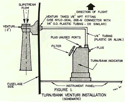
There is a Venturi size to fit most requirements. The smallest is the 2" Venturi. Oddly enough, a 2" Venturi is not indicative of its physical dimension but rather a measure of its suction producing capacity, 2" Hg. This small Venturi provides exactly enough suction to drive the gyro in a Turn/Bank Indicator. Since the small 2" Venturi can produce no more than 2" Hg, no Suction Regulator or Needle Valve is required. For that matter, a Vacuum Gage is not needed for the same reason. Figure 1 shows how simple a Turn/Bank installation can be. And since its gyro won't tumble, the instrument is a very dependable ace-in-the-hole for anyone caught accidentally in the clouds.
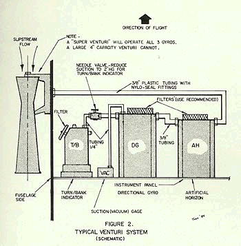
A 4" Venturi develops 4" Hg of suction within a horn that is about 10" long. It will provide just enough suction to drive a Directional Gyro and a Turn/Bank Indicator or it can be used to operate a single Artificial Horizon.
The Super Venturi has a bigger horn and is, therefore, capable of driving all three gyros.
Installation Notes For A Venturi System
The best chance of getting a good flow of air through a Venturi is to mount it on the left side of the fuselage. This arrangement applies to any conventional aircraft powered by a standard aircraft engine whose prop turns clockwise (as viewed from the cockpit). The opposite side of the fuselage would be selected for most VW powered aircraft as theirs rotates in the opposite direction.
Locate the Venturi on the left side of the fuselage in an area of undisturbed airflow. Do not, for example, mount it immediately aft of a cowling that has a gill-like outlet, or mount it under the fuselage too close to the deflected air outlet typical of many aircraft. If you must mount it near one of these locations you may have to block the Venturi away from the fuselage so that the undisturbed slipstream can enter it.
Although a Venturi system will provide you with a relatively low cost and simple installation, it is not recommended for extensive IFR operations. For one thing, a Venturi is designed to produce the necessary suction at approximately 100 mph. Since airspeeds can vary greatly the gyro rotors will be subject to varying speeds ranging from too slow to excessive. Furthermore, flown in icing conditions, your Venturi will quickly acquire the appearance of an ice cream cone and cease functioning as a vacuum source. A Venturi system is, however, good enough for incidental instrument work and under-the-hood practice.
Basic Precautions For Vacuum System Installers
Always handle your gyro instruments carefully. They are very shock sensitive and can be easily damaged.
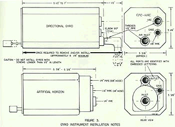
Gyro instruments, like most other aircraft instruments, are normally secured to the panel with brass instrument screws. One important difference. The screws used to attach the Directional Gyro and the Artificial Horizon must be no longer than ½" or internal damage may be done to the instrument. At any rate, read the printed information normally found on gyro instruments and abide by the instructions.
Before you begin handling the instruments for installation be sure to plug or cover all openings with duct tape. Don't open the ports until you are ready to make the connections.
Torque your plumbing fittings snugly but not excessively . . . about 25 inch pounds would be right. Better yet, install each fitting finger tight and then tighten it with a wrench no more than one and a half turns to reach the proper alignment needed. Don't use any thread lubricant, Teflon tape, etc. - especially if a Dry Vacuum Pump is installed.
Avoid making sharp bends in hoses as kinks might develop that could shut off or restrict the flow of air to the gyros.
Installation Notes
Actually, the installation of two or three gyros is relatively uncomplicated. What can make it somewhat complicated is the typical lack of space behind most homebuilt instrument panels. This is especially true of those aircraft that have a fuel tank up front. If during the early stages of construction you can decide that you will install gyros, you may stave off installation difficulties by moving the instrument panel back away from the fuel tank to provide the necessary minimum space needed by the longest instrument (Directional Gyro). The space required is approximately 8" to 8 ½" '(check the instrument you will use and allow for the fittings).
Hoses, Lines and Fittings
Do not use lines- in your vacuum system smaller than ¼" for the Turn/Bank nor smaller than 3/8" for the other instruments. Instrument manufacturers prefer the use of even larger lines as they allow their instruments to perform with greater efficiency. For this same reason, the fittings you use should not unduly restrict the inside diameter.
Nylo-seal plastic fittings are adequate for simple VFR installations but the Airborne Low-Loss fittings (manufactured by Airborne) are considered the best in the business. I can't say much for the use of standard AN fittings and aluminum tubing. Their installation is difficult when used with flared fittings because the tubing has to be precisely cut and bent just so. Furthermore, vibration may cause such an installation to develop cracks and leak.
The Vacuum Pump
Before you install that engine driven Vacuum Pump be sure it is the correct model for your engine. Pump rotation can be either clockwise ("cw") after the model number or counter clockwise ("cc"). Some pumps can rotate in either direction. Direction of rotation is established as viewing the engine drive pad or by looking at the pump from its anti-drive end.
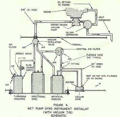
Be sure the Pump-Drive Oil Seal is in the engine and that it is in good shape. If oil leaks into a dry Vacuum Pump damage will result.
Place a mounting pad gasket in position over the crankcase studs and then install the Vacuum Pump. Be sure all ports and fittings are open and caps are removed. Then before making any plumbing connections, start the engine and check to be sure there is no oil in the discharge air. Dry pumps can be damaged if oil leaks past an engine drive oil seal and enters the pump. For this reason you should be very careful to assure yourself that all lines installed are perfectly clean and free of oil or solvents.
Should you have one of the older (better?) Wet Vacuum Pumps, its installation is quite similar. Place a Pump Mounting Pad Gasket in place over the studs and then coat the Vacuum Pump drive splines lightly with a high temperature grease -Dow Silicon #30, for example. After the pump is secured in place, start the engine and check to see that there ARE signs of oil in the air discharge. This is a Wet Pump and it relies on engine oil for proper lubrication. While the engine is running, hold a piece of paper over the air discharge port to get some idea of the amount of oil being passed . . . about 4 ounces per hour is considered normal. With a Wet Pump you will have to install an Oil Separator and a return oil line to the crankcase. The other Oil Separator outlet is connected to a vent line that expells the Vacuum Pump air overboard.
Filters
Gyro instruments are very sensitive to contaminants and dirt. For this reason gyro instruments have to be protected by filters! A Vacuum Turn/Bank Indicator has its own Filter which screws into the top port in the instrument. The Filter is a flat mushroom-like gadget the size of a silver dollar.
The other instruments are normally protected by the installation of a large Central Air Filter. These filters can effectively filter out contaminants and particles in the air too small for the naked eye to see . . . about .3 microns, and that's tiny! Air enters the Central Filter and flows on into the gyro instrument Inlets because of the suction created by the Vacuum Pump or Venturi.
Mount the Central Filter any place inside the aircraft where the air is fairly clean. Should you or your passenger smoke, be advised that smoke raises the dickens with gyro rotors. If smoking is permitted in your airplane and you are gyro equipped, it may be necessary to change the Filter more often than the customary each 100 hours of operation. Any time you see a vacuum pressure drop on the gage, think of the Filter - it could be dirty.
Vacuum Regulating Valve (Suction Regulator)
The most common type of Suction Regulator is one that is installed at the firewall from inside the aircraft. It must be adjusted to allow just enough air to enter the system. This is generally accepted to be 5.3" Hg, plus or minus .1" Hg (a range of 4.6" to 5.4 Hg is O.K.).
If a vacuum driven Turn/Bank Indicator is installed, you will also have to have a Needle Valve (Restrictor Valve) to further reduce the pressure to the TB as it only requires 1.8" Hg to perform its best. Some Vacuum Regulators have a bleed-through orifice that can also provide the required reduced vacuum to the Turn/Bank Indicator . . . all this is one Vacuum Regulator.
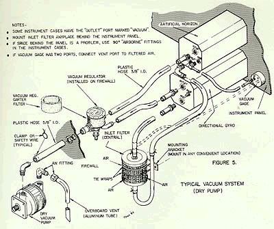
Suction Gage
Any complete gyro instrument system should have a Vacuum Gage to permit the system vacuum to be adjusted to the proper level and to monitor it. Some gages have but one port which can be connected by a line to any of the gyro instruments. If the gage has two ports it is designed to measure the pressure differential across a gyro instrument. A drop in pressure in the Differential Pressure Gage is an indication of a clogged or dirty Filter. A simple one port suction gage will not alert you to this problem as it only measures the suction pressure in the system whether or not there is any flow through the gyro instruments. See Figures 2, 4 and 5 for examples of both types.
Summary
I think you will agree that the installation of a vacuum system is not so complicated after all.
Be careful that no contaminants are allowed to enter the system during installation and watch out for kinked hoses. Use serviceable or new instruments and follow the manufacturer's instructions and you just may get your moneys worth.
