Rewiring a Sonerai
By Bill Evans, EAA 794228, EAA Chapter 266
March 2017 - It occurred to us that kit aircraft can be engineered to be simpler than plans-built aircraft, because the kit is expected to be both complete and comprehensive. Little or no engineering is expected on the part of the builder. The Sonerai I and II are not quite like that.
Installing a J3300 engine and Hoerner wingtips has raised a worksheet now 53 items long. Some of those items involve six subpoints. At this point in time, 32 items are complete on our Sonerai IILS. Yesterday was a good example of what’s involved for electrical power. Steven Craig came out to our place yesterday to help rewire the cockpit for the new engine and the Hoerner wingtips. It was for me a very full day.
With the J2200 engine there were four cockpit systems switches: comm, GPS, fuel boost pump, and strobe lights. The J3300 engine, configured as we have it, also requires: electric carb anti-ice/deice, fuel transfer pump, fuel quantity indication, and electric stabilizer trim. Stabilizer trim will have both a directional up/down switch and an on/off switch.
The stabilizer issue is inadvertent movement. We only ever needed to operate the stabilizer trim once in flight. While the movement was minute, it occurred so quickly that the aircraft appeared to jump a tiny bit. Thus an on/off guarded switch makes a great deal of sense to us. Aircraft are not supposed to jump. As an aside, there is also a modest elevator trim system. That trim tab is 3 inches by 12 inches and is sufficient for a given aircraft loading. Add a passenger, then the stabilizer needs to be trimmed. Fortunately, stabilizer trim can be done during preflight.
With the J2200 engine, individual fuses and fuse holders were originally placed in the same small panel as the switches. In short, that panel was maxed-out. Further, the one time we had to do some work in that area, the close proximity of the 10 components there made accidental shorts more problematic. You’d almost need to mold everything in silicone after soldering to be safe.
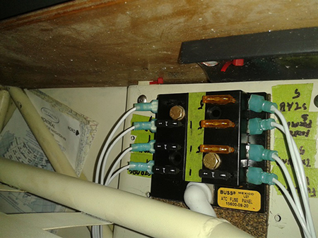
New PGS fuse block
Thus, when the J3300 engine and Hoerner wingtips, etc. were made, it became necessary to install a better fuse panel and make is easily accessible but separate from the cockpit switch panel. This involves an eight-position fuse block in groups of four. One side of the block contains all the fuel system fuses while the opposite fuse bank contains everything else. Tape labels are used for now, but P-touch labels will be made later. All the fuses are 1 amp except the two pumps, stabilizer trim, and carb heat, which are 5 amps. System tests will determine the final fuse sizes. In theory, a fuse could be replaced in flight but because of the neutral stability of the Sonerai; that’s not ever practical. A small supply of spare fuses is provided in the aircraft’s flight bag to be used on the ground.
You can see the fuse block installed in the photo. Cheap parts will not do for a main fuse block. The wiring and lugs are Teflon-coated aircraft grade.
We previously purchased a $100 pair of crimping pliers. Further, for many of the lugs, the bare wire end was folded back to fill the lug, which ensures a really solid crimp. The lugs were also firmly pulled and wiggled after crimping to be sure they can’t come off or wiggle in the lug.
Why so careful? Forty years ago we had some smoke in the cockpit from an ADF power supply. This was during a Class 1, 400-foot and 1-mile heavy ILS back course approach at YUL (Dorval). As it was, the runway wasn’t visible until touchdown, since it was raining hard. Because the ADF was switched off, it meant that we lost the final approach fix from Mirabel. Thus ATC gave us the final descent point. This was a back course ILS. No glideslope. Mercifully we saw the high intensity approach lights about 2 miles out and the runway lights before touchdown. YUL was my alternate with no fuel for another alternate. So we landed. My shirt was soaked. That’s how we learned how bad cockpit smoke is. Cockpit smoke always occurs at the worst possible time. With the new fuse panel installed, the next step is to make up a new switch panel and install the eight switches. We like to have the switch levers in different colors, but the same colors are now in use. We have good-quality enamel paints to color and switches that don’t have suitable bayonet urethane covers.
We will fabricate lightweight hinged covers for both the switch and fuse panels. The fuse panel needs a dust cover and the switch panel needs a cover to prevent inadvertent switch operation. In flight the switches are just above our right elbow, which is the arm used to fly the airplane.
The microswitches work just fine for portable avionics power supplies, strobes, and gauges. Carb heat and fuel pumps might draw about 5 amps. In extended use, the microswitches could overheat, so we’ll revert to AN switches with the screw attachments for the terminal lugs.
This fuse panel installation and all the related bits had been a problem for about two years. While we had all the parts, the devil was in the details. The why and how and where of it were unresolved. How can one run the wiring for carb heat, transfer pump, etc. when you don’t know where the fuses and switches will be located. Steven contributing his Saturday meant that all those decisions are made and the great majority of the electrical work is completed. The problem is solved.
